SHIFT LEVER REASSEMBLY
PROCEDURE
-
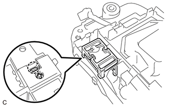
INSTALL POSITION INDICATOR LENS
-
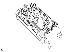
Engage the 4 claws to install the position indicator lens.
-
-
INSTALL NO. 2 POSITION INDICATOR SLIDE COVER
-
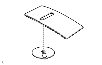
Install the No. 2 position indicator slide cover to the position indicator slide cover.
-
-
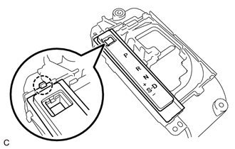
INSTALL POSITION INDICATOR SLIDE COVER
-
Install the position indicator slide cover to the upper position indicator housing.
-
-
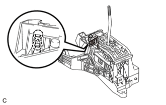
INSTALL INDICATOR LIGHT WIRE SUB-ASSEMBLY
-
Install the 2 caps to the 2 bulbs.
-
Install the 2 bulbs to the indicator light wire sub-assembly.
-
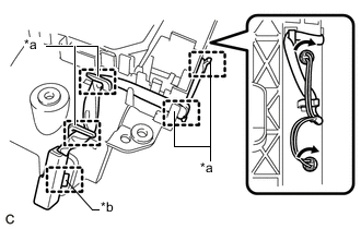
Text in Illustration *a Guide *b Clamp Connect the 4 guides, clamp and 2 bulb sockets to install the indicator light wire sub-assembly to the upper position indicator housing.
-
-
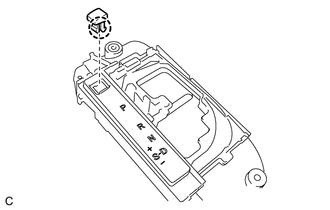
INSTALL SHIFT LOCK RELEASE BUTTON (Shift Position Indicator Side)
-
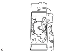
Engage the claw to install the shift lock release button to the upper position indicator housing with the shift lock release spring.
-
Engage the claw to install the position indicator plate to the upper position indicator housing.
-
-
INSTALL SHIFT LOCK RELEASE BUTTON COVER
-
Engage the 2 claws to install the shift lock release button cover to the position indicator plate.
-
-
INSTALL SHIFT POSITION INDICATOR
-
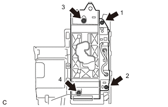
Install the shift position indicator to the rear console upper panel sub-assembly with the 4 screws in the sequence shown in the illustration.
-
-
INSTALL SHIFT LOCK RELEASE BUTTON (Lower Shift Lever Assembly Side)
-
Engage the 2 claws to install the shift lock release button and shift lock release spring to the shift lever assembly.
-
-
INSTALL LOWER POSITION INDICATOR HOUSING
-
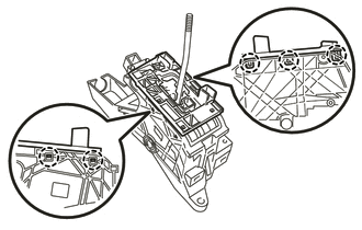
Engage the 5 claws to install the lower position indicator housing to the shift lever assembly.
-