Info Added 2017-08-02
PROCEDURE
- Click here
INSTALL SHIFT LEVER POSITION SENSOR
-
Install the shift lever position sensor to the manual valve shaft.
-
Temporarily install the 2 bolts.
-
Install a new lock plate and tighten the nut.
6.9 N*m 70 kgf*cm 61 in.*lbf -
Temporarily install the control shaft lever to the manual valve shaft.
-
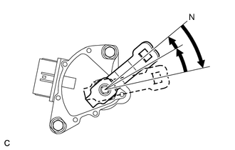
Turn the control shaft lever clockwise until it stops, then turn it counterclockwise 2 notches.
-
Remove the control shaft lever from the manual valve shaft.
-
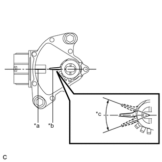
Align the protruding part with the neutral basic line.
Table 1. Text in Illustration *a Neutral Basic Line *b Protruding Part *c Range of Play Note:There is play on the nut stopper side (protruding part). Align the center point of the range of play with the neutral basic line.
-
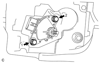
Tighten the 2 bolts in the order shown in the illustration.
13 N*m 133 kgf*cm 10 ft.*lbf -
Using a screwdriver, secure the nut with the lock plate.
-
Install the control shaft lever, washer and nut to the manual valve shaft.
13 N*m 130 kgf*cm 9 ft.*lbf -
Connect the shift lever position sensor connector.
-
- Click here
CONNECT TRANSMISSION CONTROL CABLE ASSEMBLY
-
Move the shift lever to N.
-
Install a new clip to the No. 1 transmission control cable bracket.
-
Install the transmission control cable assembly to the No. 1 transmission control cable bracket.
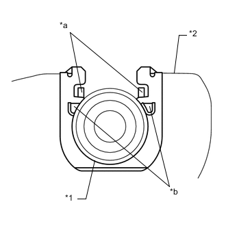
Table 2. Text in Illustration *1 Transmission Control Cable Assembly *2 No. 1 Transmission Control Cable Bracket *a Claw A *b Claw B Note:
-
Make sure that the claws A on the clip are securely fit into the bracket holes.
-
Make sure that the cable is securely installed inside the claws B of the clip.
-
-
Connect the transmission control cable assembly to the control shaft lever with the nut.
13 N*m 130 kgf*cm 9 ft.*lbf
-
- Click here
INSPECT SHIFT LEVER POSITION SENSOR POSITION
- Click here
ADJUST SHIFT LEVER POSITION SENSOR POSITION
- Click here
INSPECT SHIFT LEVER POSITION
- Click here
ADJUST SHIFT LEVER POSITION
- Click here
INSTALL ENGINE UNDER COVER LH (w/o Front Lower Bumper Absorber)
- Click here
INSTALL ENGINE UNDER COVER LH (w/ Front Lower Bumper Absorber)
- Click here
INSTALL FRONT WHEEL OPENING EXTENSION PAD LH
- Click here
INSTALL ENGINE UNDER COVER RH (w/o Front Lower Bumper Absorber)
- Click here
INSTALL ENGINE UNDER COVER RH (w/ Front Lower Bumper Absorber)
- Click here
INSTALL FRONT WHEEL OPENING EXTENSION PAD RH
- Click here
INSTALL FRONT LOWER BUMPER ABSORBER (w/ Front Lower Bumper Absorber)