SHIFT LEVER POSITION SENSOR INSTALLATION
Info Added 2017-08-02 ![]()
PROCEDURE
-
INSTALL SHIFT LEVER POSITION SENSOR
-
Install the shift lever position sensor to the manual valve shaft.
-
Temporarily install the 2 bolts.
-
Install a new lock plate and tighten the nut.
- Torque:
- 6.9 N*m { 70 kgf*cm, 61 in.*lbf }
-
Temporarily install the control shaft lever to the manual valve shaft.
-
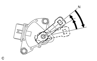
Turn the lever clockwise until it stops, then turn it counterclockwise 2 notches.
-
Remove the control shaft lever from the manual valve shaft.
-
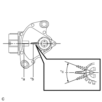
Text in Illustration *a Neutral Basic Line *b Protruding *c Range of Play Align the protruding part with the neutral basic line.
Note
There is play on the nut stopper side (protruding part). Align the center point of the range of play with the neutral basic line.
-
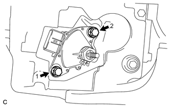
Tighten the 2 bolts in the order shown in the illustration.
- Torque:
- 13 N*m { 133 kgf*cm, 10 ft.*lbf }
-
Using a screwdriver, secure the nut with the lock plate.
-
Install the control shaft lever, washer and nut to the manual valve shaft.
- Torque:
- 13 N*m { 130 kgf*cm, 9 ft.*lbf }
-
Connect the connector to the shift lever position sensor.
-
-
CONNECT TRANSMISSION CONTROL CABLE ASSEMBLY
-
Move the shift lever to N.
-
Install a new clip to the No. 1 transmission control cable bracket.
-
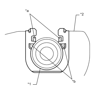
Text in Illustration *1 Transmission Control Cable Assembly *2 No. 1 Transmission Control Cable Bracket *a Claw A *b Claw B Install the transmission control cable assembly to the No. 1 transmission control cable bracket.
Note
-
Make sure that the claws A on the clip are securely fit into the bracket holes.
-
Make sure that the cable is securely installed inside the claws B of the clip.
-
-
Connect the transmission control cable assembly to the control shaft lever with the nut.
- Torque:
- 13 N*m { 130 kgf*cm, 9 ft.*lbf }
-
-
INSPECT SHIFT LEVER POSITION SENSOR POSITION
-
ADJUST SHIFT LEVER POSITION SENSOR POSITION
-
INSPECT SHIFT LEVER POSITION
-
ADJUST SHIFT LEVER POSITION
-
INSTALL ENGINE UNDER COVER LH
-
INSTALL FRONT WHEEL OPENING EXTENSION PAD LH
-
INSTALL ENGINE UNDER COVER RH
-
INSTALL FRONT WHEEL OPENING EXTENSION PAD RH