LANE DEPARTURE ALERT SYSTEM(w/ Steering Control) Steering Pad Switch Circuit
DESCRIPTION
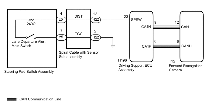
The driving support ECU assembly receives a lane departure alert main switch signal from the steering pad switch assembly and sends the signal to the forward recognition camera via CAN communication.
WIRING DIAGRAM
CAUTION / NOTICE / HINT
Note
The vehicle is equipped with a Supplemental Restraint System (SRS) which includes components such as airbags. Before servicing (including removal or installation of parts), be sure to read the precaution for Supplemental Restraint System Click here.
PROCEDURE
-
READ VALUE USING GTS (CAN BUS CHECK)
-
Connect the GTS to the DLC3.
-
Turn the power switch on (IG).
-
Turn the GTS on.
-
Enter the following menus: System Select / Can Bus Check.
Result Result Proceed to All of the ECUs and sensors that are currently connected to the CAN communication system are displayed. A None of the ECUs and sensors that are currently connected to the CAN communication system are displayed, or some of them are not displayed. B -
Turn the power switch off.
B 
GO TO CAN COMMUNICATION SYSTEM Click here
A 
-
-
CHECK FOR DTCs (HEALTH CHECK)
-
Connect the GTS to the DLC3.
-
Turn the power switch on (IG).
-
Turn the GTS on.
-
Enter the following menus: System Select / Health Check.
-
Check DTCs.
Result Result Proceed to No DTCs are output. A DTCs are output. B -
Turn the power switch off.
B
GO TO DTC CHART
A
-
-
INSPECT STEERING PAD SWITCH ASSEMBLY
-
Remove the horn button assembly Click here.
-
Disconnect the steering pad switch assembly connector.
-
Measure the resistance according to the value(s) in the table below.
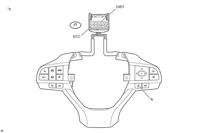
Text in Illustration *a Component without harness connected
(Steering Pad Switch Assembly)
*b Lane Departure Alert Main Switch Standard Resistance Tester Connection Condition Specified Condition z5-4 (DIST) - z5-7 (ECC) Lane departure alert main switch being pushed and held 228 to 252 Ω Lane departure alert main switch not pushed 10 kΩ or higher -
Reconnect the steering pad switch assembly connector.
-
Reinstall the horn button assembly Click here.
NG
REPLACE STEERING PAD SWITCH ASSEMBLY Click here
OK
-
-
INSPECT SPIRAL CABLE WITH SENSOR SUB-ASSEMBLY
-
Inspect the spiral cable with sensor sub-assembly Click here.
NG
REPLACE SPIRAL CABLE WITH SENSOR SUB-ASSEMBLY Click here
OK
-
-
CHECK HARNESS AND CONNECTOR (SPIRAL CABLE WITH SENSOR SUB-ASSEMBLY - DRIVING SUPPORT ECU ASSEMBLY)
-
Disconnect the H22 spiral cable with sensor sub-assembly connector.
-
Disconnect the H196 driving support ECU assembly connector.
-
Measure the resistance according to the value(s) in the table below.
Standard Resistance (Check for Open) Tester Connection Condition Specified Condition H22-12 (DIST) - H196-23 (SPSW) Always 3 Ω or less Standard Resistance (Check for Short) Tester Connection Condition Specified Condition H22-12 (DIST) or H196-23 (SPSW) - Body ground Always Below 1 Ω -
Reconnect the H196 driving support ECU assembly connector.
-
Reconnect the H22 spiral cable with sensor sub-assembly connector.
NG
REPAIR OR REPLACE HARNESS OR CONNECTOR
OK
-
-
CHECK HARNESS AND CONNECTOR (SPIRAL CABLE WITH SENSOR SUB-ASSEMBLY - BODY GROUND)
-
Disconnect the H22 spiral cable with sensor sub-assembly connector.
-
Measure the resistance according to the value(s) in the table below.
Standard Resistance (Check for Open) Tester Connection Condition Specified Condition H22-2 (ECC) - Body ground Always Below 1 Ω -
Reconnect the H22 spiral cable with sensor sub-assembly connector.
OK
PROCEED TO NEXT SUSPECTED AREA SHOWN IN PROBLEM SYMPTOMS TABLE Click here
NG
REPAIR OR REPLACE HARNESS OR CONNECTOR
-