LANE DEPARTURE ALERT SYSTEM(w/o Dynamic Radar Cruise Control System), Diagnostic DTC:C1AA7
| DTC Code | DTC Name |
|---|---|
| C1AA7 | Skid Control Buzzer Circuit |
DESCRIPTION
The lane departure warning camera sends a buzzer request signal to the skid control buzzer assembly to sound the buzzer. When the lane departure warning camera detects a malfunction in the skid control buzzer circuit, the lane departure warning camera stores DTC C1AA7.
| DTC Code | DTC Detection Condition | Trouble Area |
|---|---|---|
| C1AA7 | Both of the following conditions are met:
|
|
WIRING DIAGRAM
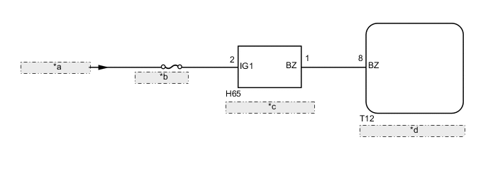
| *a | from IG1 NO. 4 Relay |
| *b | ECU-IG1 NO. 3 |
| *c | Skid Control Buzzer Assembly |
| *d | Lane Departure Warning Camera |
CAUTION / NOTICE / HINT
Note
-
When the lane departure warning camera is replaced with a new one, adjustment of the lane departure warning camera beam axis must be performed Click here.
-
Inspect the fuses for circuits related to this system before performing the following inspection procedure.
PROCEDURE
-
CHECK HARNESS AND CONNECTOR (POWER SOURCE VOLTAGE)
-
Disconnect the H65 skid control buzzer assembly connector.
-
Turn the power switch on (IG).
-
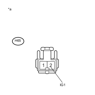
Text in Illustration *a Front view of wire harness connector
(to Skid Control Buzzer Assembly)
Measure the voltage according to the value(s) in the table below.
Standard Voltage Tester Connection Condition Specified Condition H65-2 (IG1) - Body ground Power switch on (IG) 11 to 14 V -
Turn the power switch off.
-
Reconnect the H65 skid control buzzer assembly connector.
NG 
CHECK POWER SOURCE CIRCUIT
OK 
-
-
INSPECT SKID CONTROL BUZZER ASSEMBLY
-
Remove the skid control buzzer assembly Click here.
-
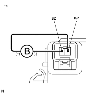
Text in Illustration *a Component without harness connected
(Skid Control Buzzer Assembly)
Connect a negative (-) lead from the auxiliary battery to terminal 1 (BZ), and a positive (+) lead to terminal 2 (IG1) of the skid control buzzer assembly, and then check that the buzzer sounds.
OK The skid control buzzer assembly sounds. -
Reinstall the skid control buzzer assembly.
NG
REPLACE SKID CONTROL BUZZER ASSEMBLY Click here
OK
-
-
CHECK HARNESS AND CONNECTOR (LANE DEPARTURE WARNING CAMERA - SKID CONTROL BUZZER ASSEMBLY)
-
Disconnect the T12 lane departure warning camera connector.
-
Disconnect the H65 skid control buzzer assembly connector.
-
Measure the resistance according to the value(s) in the table below.
Standard Resistance Tester Connection Condition Specified Condition T12-8 (BZ) - H65-1 (BZ) Always Below 1 Ω T12-8 (BZ) or H65-1 (BZ) - Body ground Always 10 kΩ or higher -
Reconnect the H65 skid control buzzer assembly connector.
-
Reconnect the T12 lane departure warning camera connector.
OK
REPLACE LANE DEPARTURE WARNING CAMERA Click here
NG
REPAIR OR REPLACE HARNESS OR CONNECTOR
-