LANE DEPARTURE ALERT SYSTEM(w/o Dynamic Radar Cruise Control System) Steering Pad Switch Circuit
DESCRIPTION
The lane departure warning camera receives a lane departure alert main switch signal from the steering pad switch assembly.
WIRING DIAGRAM
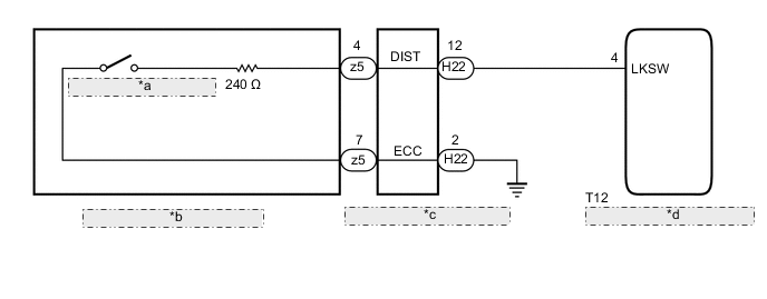
| *a | Lane Departure Alert Main Switch |
| *b | Steering Pad Switch Assembly |
| *c | Spiral Cable with Sensor Sub-assembly |
| *d | Lane Departure Warning Camera |
PROCEDURE
-
INSPECT STEERING PAD SWITCH ASSEMBLY
-
Remove the horn button assembly Click here.
-
Disconnect the z5 spiral cable with sensor sub-assembly connector.
-
Measure the resistance according to the value(s) in the table below.
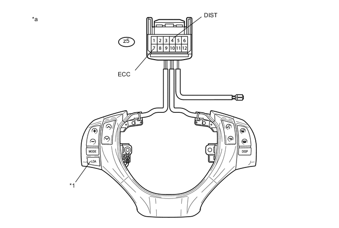
Text in Illustration *1 Lane Departure Alert Main Switch - - *a Component without harness connected
(Steering Pad Switch Assembly)
- - Standard Resistance Tester Connection Condition Specified Condition z5-4 (DIST) - z5-7 (ECC) Lane departure alert main switch being pushed and held 228 to 252 Ω Lane departure alert main switch not pushed 10 kΩ or higher -
Reconnect the z5 spiral cable with sensor sub-assembly connector.
-
Reinstall the horn button assembly Click here.
NG 
REPLACE STEERING PAD SWITCH ASSEMBLY Click here
OK 
-
-
INSPECT SPIRAL CABLE WITH SENSOR SUB-ASSEMBLY
Note
The spiral cable with sensor sub-assembly is an important part of the SRS airbag system. Incorrect removal or installation of the spiral cable with sensor sub-assembly may cause airbag deployment. Be sure to read the pages shown in the brackets.
-
Remove the spiral cable with sensor sub-assembly.
-
Measure the resistance according to the value(s) in the table below.
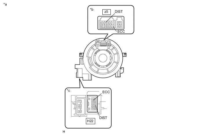
Standard Resistance Tester Connection Condition Specified Condition z5-4 (DIST) - H22-12 (DIST) The spiral cable with sensor sub-assembly position is center 3 Ω or less The spiral cable with sensor sub-assembly position is 2.5 rotations to the left The spiral cable with sensor sub-assembly position is 2.5 rotations to the right z5-7 (ECC) - H22-2 (ECC) The spiral cable with sensor sub-assembly position is center 3 Ω or less The spiral cable with sensor sub-assembly position is 2.5 rotations to the left The spiral cable with sensor sub-assembly position is 2.5 rotations to the right Text in Illustration *a Component without harness connected
(Spiral Cable with Sensor Sub-assembly)
*b Steering Pad Switch Assembly Side *c Vehicle Side Tech Tips
The spiral cable with sensor sub-assembly makes a maximum of approximately 5 rotations.
-
After setting the spiral cable with sensor sub-assembly to the center position, rotate the spiral cable with sensor sub-assembly 2.5 times clockwise. Then while rotating the spiral cable with sensor sub-assembly 5 times counterclockwise, measure the resistance according to the value(s) in the table below.
Standard Resistance Tester Connection Condition Specified Condition z5-4 (DIST) - H22-12 (DIST) Always 3 Ω or less z5-7 (ECC) - H22-2 (ECC) Always 3 Ω or less Tech Tips
The spiral cable with sensor sub-assembly makes a maximum of approximately 5 rotations.
-
Reinstall the spiral cable with sensor sub-assembly.
NG
REPLACE SPIRAL CABLE WITH SENSOR SUB-ASSEMBLY Click here
OK
-
-
CHECK HARNESS AND CONNECTOR (SPIRAL CABLE WITH SENSOR SUB-ASSEMBLY - LANE DEPARTURE WARNING CAMERA)
-
Disconnect the H22 spiral cable with sensor sub-assembly connector.
-
Disconnect the T12 lane departure warning camera connector.
-
Measure the resistance according to the value(s) in the table below.
Standard Resistance (Check for Open) Tester Connection Condition Specified Condition H22-12 (DIST) - T12-4 (LKSW) Always 3 Ω or less Standard Resistance (Check for Short) Tester Connection Condition Specified Condition H22-12 (DIST) or T12-4 (LKSW) - Body ground Always 1 MΩ or higher -
Reconnect the T12 lane departure warning camera connector.
-
Reconnect the H22 spiral cable with sensor sub-assembly connector.
NG
REPAIR OR REPLACE HARNESS OR CONNECTOR
OK
-
-
CHECK HARNESS AND CONNECTOR (SPIRAL CABLE WITH SENSOR SUB-ASSEMBLY - BODY GROUND)
-
Disconnect the H22 spiral cable with sensor sub-assembly connector.
-
Measure the resistance according to the value(s) in the table below.
Standard Resistance (Check for Open) Tester Connection Condition Specified Condition H22-2 (ECC) - Body ground Always Below 1 Ω -
Reconnect the H22 spiral cable with sensor sub-assembly connector.
OK
PROCEED TO NEXT SUSPECTED AREA SHOWN IN PROBLEM SYMPTOMS TABLE Click here
NG
REPAIR OR REPLACE HARNESS OR CONNECTOR
-