DYNAMIC RADAR CRUISE CONTROL SYSTEM, Diagnostic DTC:P0571
| DTC Code | DTC Name |
|---|---|
| P0571 | Brake Switch "A" Circuit |
DESCRIPTION
-
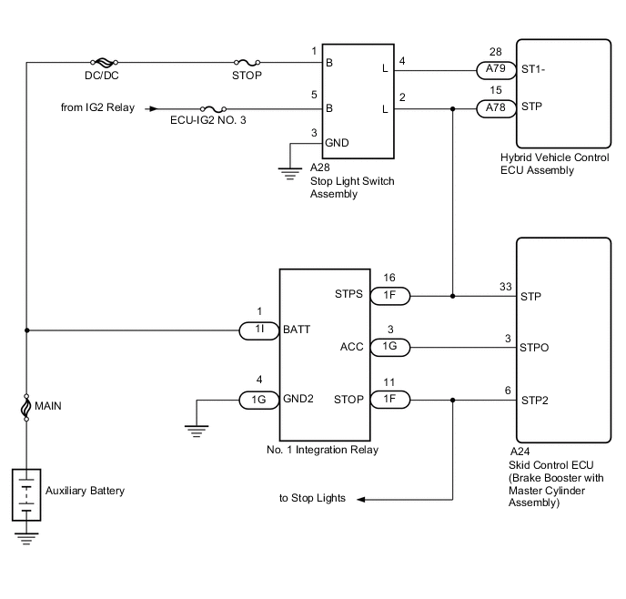
When the brake pedal is depressed, the stop light switch assembly sends a signal to the hybrid vehicle control ECU assembly. When the hybrid vehicle control ECU assembly receives this signal, it cancels the dynamic radar cruise control. The fail-safe function operates to enable normal driving even if there is a malfunction in the stop light signal circuit. The cancellation condition occurs when voltage is applied to terminal STP. When the brake is applied, voltage is normally applied to terminal STP of the hybrid vehicle control ECU assembly through the STOP fuse and the stop light switch assembly, and the hybrid vehicle control ECU assembly turns the dynamic radar cruise control system off.
-
The hybrid vehicle control ECU assembly receives the brake demand signal from the driving support ECU assembly and transmits it to the skid control ECU (brake booster with master cylinder assembly). The skid control ECU (brake booster with master cylinder assembly) receives a signal from the hybrid vehicle control ECU assembly and operates the skid control ECU (brake booster with master cylinder assembly). The skid control ECU (brake booster with master cylinder assembly) operates the brake booster with master cylinder assembly and at the same time illuminates the stop light by operating the No. 1 integration relay.
| DTC No. | DTC Detection Condition | Trouble Area |
|---|---|---|
| P0571 | When the power switch is on (IG) and the dynamic radar cruise control system is operating, voltage of STP terminal and that of ST1- terminal of hybrid vehicle control ECU assembly are less than 1 V for approximately 0.5 seconds or more. |
|
| While the dynamic radar cruise control system is operating (vehicle-to-vehicle distance control mode), the hybrid vehicle control ECU assembly detects the No. 1 integration relay error signal from the skid control ECU (brake booster with master cylinder assembly) for approximately 0.2 seconds or more. |
|
WIRING DIAGRAM
CAUTION / NOTICE / HINT
Tech Tips
Inspect the fuses for circuits related to this system before performing the following inspection procedure.
PROCEDURE
-
CHECK STOP LIGHT OPERATION
-
Check that the stop lights come on when the brake pedal is depressed, and go off when the brake pedal is released.
OK Condition Illumination Condition Brake pedal depressed ON Brake pedal released OFF
NG 
GO TO LIGHTING SYSTEM (EXT) Click here
OK 
-
-
READ VALUE USING GTS (STOP LIGHT SWITCH)
-
Connect the GTS to the DLC3.
-
Turn the power switch on (IG).
-
Turn the GTS on.
-
Enter the following menus: Powertrain / Hybrid Control / Data List.
-
Check the Data List for proper functioning of the stop light switch.
Hybrid Control Tester Display Measurement Item/Range Normal Condition Diagnostic Note Stop Light Switch Stop light switch status / ON or OFF ON: Brake pedal depressed
OFF: Brake pedal released
- OK Display changes according to brake pedal operation described in above table. -
Turn the power switch off.
NG 
CHECK HARNESS AND CONNECTOR (STOP LIGHT SWITCH POWER SOURCE CIRCUIT) Click here
OK
-
-
CHECK HARNESS AND CONNECTOR (STOP LIGHT SWITCH ASSEMBLY - SKID CONTROL ECU)
-
Disconnect the A28 stop light switch assembly connector.
-
Disconnect the A24 skid control ECU (brake booster with master cylinder assembly) connector.
-
Measure the resistance according to the value(s) in the table below.
Standard Resistance (Check for Open) Tester Connection Condition Specified Condition A28-2 (L) - A24-33 (STP) Always Below 1 Ω Standard Resistance (Check for Short) Tester Connection Condition Specified Condition A28-2 (L) or A24-33 (STP) - Body ground Always 10 kΩ or higher -
Reconnect the A24 skid control ECU (brake booster with master cylinder assembly) connector.
-
Reconnect the A28 stop light switch assembly connector.
NG
REPAIR OR REPLACE HARNESS OR CONNECTOR
OK
-
-
CHECK HARNESS AND CONNECTOR (NO. 1 INTEGRATION RELAY - SKID CONTROL ECU)
-
Disconnect the 1F and 1G No. 1 integration relay connectors.
-
Disconnect the A24 skid control ECU (brake booster with master cylinder assembly) connector.
-
Measure the resistance according to the value(s) in the table below.
Standard Resistance (Check for Open) Tester Connection Condition Specified Condition 1F-11 (STOP) - A24-6 (STP2) Always Below 1 Ω 1F-16 (STPS) - A24-33 (STP) Always Below 1 Ω 1G-3 (ACC) - A24-3 (STPO) Always Below 1 Ω Standard Resistance (Check for Short) Tester Connection Condition Specified Condition 1F-11 (STOP) or A24-6 (STP2) - Body ground Always 10 kΩ or higher 1F-16 (STPS) or A24-33 (STP) - Body ground Always 10 kΩ or higher 1G-3 (ACC) or A24-3 (STPO) - Body ground Always 10 kΩ or higher -
Reconnect the A24 skid control ECU (brake booster with master cylinder assembly) connector.
-
Reconnect the 1F and 1G No. 1 integration relay connectors.
NG
REPAIR OR REPLACE HARNESS OR CONNECTOR
OK
-
-
INSPECT NO. 1 INTEGRATION RELAY
NG
REPLACE NO. 1 INTEGRATION RELAY Click here
OK
-
REPLACE BRAKE BOOSTER WITH MASTER CYLINDER ASSEMBLY
(See page for LHD, Click here for RHD)
NEXT
-
CHECK FOR DTCs (DTC P0571)
-
Connect the GTS to the DLC3.
-
Turn the power switch on (IG).
-
Clear the DTCs Click here.
-
Make sure that the DTC detection conditions are met.
Tech Tips
If the detection conditions are not met, the system cannot detect the malfunction.
-
Enter the following menus: Powertrain / Radar Cruise1 / Trouble Codes.
-
Check for DTCs.
Result Result Proceed to DTC is not output A DTC P0571 is output B -
Turn the power switch off.
A
END
B
REPLACE HYBRID VEHICLE CONTROL ECU ASSEMBLY Click here
-
-
CHECK HARNESS AND CONNECTOR (STOP LIGHT SWITCH POWER SOURCE CIRCUIT)
-
Disconnect the A28 stop light switch assembly connector.
-
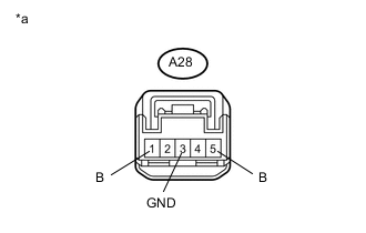
Text in Illustration *a Front view of wire harness connector
(to Stop Light Switch Assembly)
Measure the voltage and resistance according to the value(s) in the table below.
Standard Voltage Tester Connection Condition Specified Condition A28-1 (B) - A28-3 (GND) Power switch off 11 to 14 V A28-5 (B) - A28-3 (GND) Power switch on (IG) 11 to 14 V Standard Resistance Tester Connection Condition Specified Condition A28-3 (GND) - Body ground Always Below 1 Ω -
Reconnect the A28 stop light switch assembly connector.
NG
REPAIR OR REPLACE HARNESS OR CONNECTOR
OK
-
-
INSPECT STOP LIGHT SWITCH ASSEMBLY
-
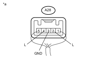
Text in Illustration *a Component with harness connected
(Stop Light Switch Assembly)
Measure the voltage according to the value(s) in the table below.
Standard Voltage Tester Connection Condition Specified Condition A28-2 (L) - A28-3 (GND) Brake pedal not depressed Below 1 V Brake pedal depressed 11 to 14 V A28-4 (L) - A28-3 (GND) Power switch on (IG), brake pedal not depressed 11 to 14 V Power switch on (IG), brake pedal depressed Below 1 V
NG
REPLACE STOP LIGHT SWITCH ASSEMBLY Click here
OK
-
-
CHECK HARNESS AND CONNECTOR (HYBRID VEHICLE CONTROL ECU ASSEMBLY - STOP LIGHT SWITCH ASSEMBLY)
-
Disconnect the A78 and A79 hybrid vehicle control ECU assembly connectors.
-
Disconnect the A28 stop light switch assembly connector.
-
Disconnect the 1F and 1G No. 1 integration relay connectors.
-
Disconnect the A24 skid control ECU (brake booster with master cylinder assembly) connector.
-
Measure the resistance according to the value(s) in the table below.
Standard Resistance (Check for Open) Tester Connection Condition Specified Condition A78-15 (STP) - A28-2 (L) Always Below 1 Ω A79-28 (ST1-) - A28-4 (L) Always Below 1 Ω Standard Resistance (Check for Short) Tester Connection Condition Specified Condition A78-15 (STP) or A28-2 (L) - Body ground Always 10 kΩ or higher A79-28 (ST1-) or A28-4 (L) - Body ground Always 10 kΩ or higher -
Reconnect the A24 skid control ECU (brake booster with master cylinder assembly) connector.
-
Reconnect the 1F and 1G No. 1 integration relay connectors.
-
Reconnect the A28 stop light switch assembly connector.
-
Reconnect the A78 and A79 hybrid vehicle control ECU assembly connectors.
OK
REPLACE HYBRID VEHICLE CONTROL ECU ASSEMBLY Click here
NG
REPAIR OR REPLACE HARNESS OR CONNECTOR
-