DYNAMIC RADAR CRUISE CONTROL SYSTEM, Diagnostic DTC:C1A05
| DTC Code | DTC Name |
|---|---|
| C1A05 | Stop Light Switch Circuit |
DESCRIPTION
When the brake pedal is depressed, the stop light switch assembly sends a brake pedal operation signal to the driving support ECU assembly. After reception of this signal, the driving support ECU assembly cancels the radar cruise control system. When the driving support ECU assembly detects a malfunction in the stop light switch circuit, DTC C1A05 is stored.
| DTC No. | DTC Detection Condition | Trouble Area |
|---|---|---|
| C1A05 | Voltages of terminals ST1- and STP- of driving support ECU assembly are both below 1 V for 1 second |
|
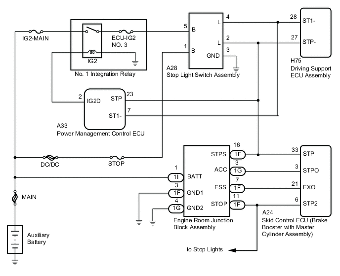
WIRING DIAGRAM
CAUTION / NOTICE / HINT
Tech Tips
Inspect the fuses for circuits related to this system before performing the following inspection procedure.
PROCEDURE
-
CHECK STOP LIGHT OPERATION
-
Check that the stop lights come on when the brake pedal is depressed, and go off when the brake pedal is released.
OK Condition Illumination Condition Brake pedal depressed ON Brake pedal released OFF
NG 
GO TO LIGHTING SYSTEM (EXT)
OK 
-
-
READ VALUE USING GTS (STOP LIGHT SW 1 (M CPU), STOP LIGHT SW 1 (S CPU), STOP LIGHT SW 2 (M CPU))
-
Connect the GTS to the DLC3.
-
Turn the power switch on (IG).
-
Turn the GTS on.
-
Enter the following menus: Powertrain / Radar Cruise / Data List.
-
Check the Data List for proper functioning of the stop light switch assembly.
Radar Cruise Tester Display Measurement Item/Range Normal Condition Diagnostic Note Stop Light SW 1 (M CPU) Stop light switch (Main-CPU) signal / ON or OFF ON: Brake pedal depressed
OFF: Brake pedal released
- Stop Light SW 1 (S CPU) Stop light switch (Sub-CPU) signal / ON or OFF ON: Brake pedal depressed
OFF: Brake pedal released
- Stop Light SW 2 (M CPU) Stop light switch (Main-CPU) signal / ON or OFF ON: Brake pedal depressed
OFF: Brake pedal released
- OK Display changes according to brake pedal operation described in the table above. -
Turn the power switch off.
NG 
CHECK HARNESS AND CONNECTOR (STOP LIGHT SWITCH ASSEMBLY POWER SOURCE CIRCUIT) Click here
OK
-
-
CHECK HARNESS AND CONNECTOR (STOP LIGHT SWITCH ASSEMBLY - SKID CONTROL ECU)
-
Disconnect the A28 stop light switch assembly connector.
-
Disconnect the A24 skid control ECU (brake booster with master cylinder assembly) connector.
-
Measure the resistance according to the value(s) in the table below.
Standard Resistance (Check for Open) Tester Connection Condition Specified Condition A28-2 (L) - A24-33 (STP) Always Below 1 Ω Standard Resistance (Check for Short) Tester Connection Condition Specified Condition A28-2 (L) or A24-33 (STP) - Body ground Always 10 kΩ or higher -
Reconnect the A24 skid control ECU (brake booster with master cylinder assembly) connector.
-
Reconnect the A28 stop light switch assembly connector.
NG
REPAIR OR REPLACE HARNESS OR CONNECTOR
OK
-
-
CHECK HARNESS AND CONNECTOR (ENGINE ROOM JUNCTION BLOCK ASSEMBLY - SKID CONTROL ECU)
-
Remove the engine room junction block assembly from the engine room relay block and junction block assembly.
-
Disconnect the A24 skid control ECU (brake booster with master cylinder assembly) connector.
-
Measure the resistance according to the value(s) in the table below.
Standard Resistance (Check for Open) Tester Connection Condition Specified Condition 1G-3 (ACC) - A24-3 (STPO) Always Below 1 Ω 1F-7 (ESS) - A24-21 (EXO) Always Below 1 Ω 1F-16 (STPS) - A24-33 (STP) Always Below 1 Ω 1F-11 (STOP) - A24-6 (STP2) Always Below 1 Ω Standard Resistance (Check for Short) Tester Connection Condition Specified Condition 1G-3 (ACC) or A24-3 (STPO) - Body ground Always 10 kΩ or higher 1F-7 (ESS) or A24-21 (EXO) - Body ground Always 10 kΩ or higher 1F-16 (STPS) or A24-33 (STP) - Body ground Always 10 kΩ or higher 1F-11 (STOP) or A24-6 (STP2) - Body ground Always 10 kΩ or higher -
Reconnect the A24 skid control ECU (brake booster with master cylinder assembly) connector.
-
Install the engine room junction block assembly to the engine room relay block and junction block assembly.
NG
REPAIR OR REPLACE HARNESS OR CONNECTOR
OK
-
-
INSPECT ENGINE ROOM JUNCTION BLOCK ASSEMBLY
NG
REPLACE ENGINE ROOM JUNCTION BLOCK ASSEMBLY Click here
OK
-
REPLACE BRAKE BOOSTER WITH MASTER CYLINDER ASSEMBLY
NEXT
-
CHECK FOR DTCs (DTC C1A05)
-
Connect the GTS to the DLC3.
-
Turn the power switch on (IG).
-
Clear the DTCs Click here.
-
Perform the following to make sure that the DTC detection conditions are met.
Tech Tips
If the detection conditions are not met, the malfunction cannot be detected.
-
Drive the vehicle at a speed for which cruise control operation is possible.
-
Turn the cruise control system on using the cruise control switch (ON-OFF button).
-
Push the cruise control switch to -/SET to begin control of vehicle speed by the dynamic radar cruise control system.
-
-
Enter the following menus: Powertrain / Radar Cruise / Trouble Codes.
-
Check for DTCs.
Result Result Proceed to DTC is not output A DTC C1A05 is output B -
Turn the power switch off.
A
END
B
-
-
REPLACE POWER MANAGEMENT CONTROL ECU
NEXT
-
CHECK FOR DTCs (DTC C1A05)
-
Connect the GTS to the DLC3.
-
Turn the power switch on (IG).
-
Clear the DTCs Click here.
-
Perform the following to make sure that the DTC detection conditions are met.
Tech Tips
If the detection conditions are not met, the malfunction cannot be detected.
-
Drive the vehicle at a speed for which cruise control operation is possible.
-
Turn the cruise control system on using the cruise control switch (ON-OFF button).
-
Push the cruise control switch to -/SET to begin control of vehicle speed using the cruise control system.
-
-
Enter the following menus: Powertrain / Radar Cruise / Trouble Codes.
-
Check for DTCs.
Result Result Proceed to DTC is not output A DTC C1A05 is output B -
Turn the power switch off.
A
END
B
REPLACE DRIVING SUPPORT ECU ASSEMBLY Click here
-
-
CHECK HARNESS AND CONNECTOR (STOP LIGHT SWITCH ASSEMBLY POWER SOURCE CIRCUIT)
-
Disconnect the A28 stop light switch assembly connector.
-
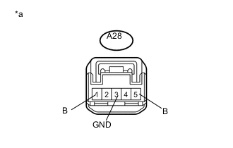
Text in Illustration *a Front view of wire harness connector
(to Stop Light Switch Assembly)
Measure the voltage according to the value(s) in the table below.
Standard Voltage Tester Connection Condition Specified Condition A28-1 (B) - A28-3 (GND) Power switch off 11 to 14 V A28-5 (B) - A28-3 (GND) Power switch ON 11 to 14 V -
Measure the resistance according to the value(s) in the table below.
Standard Resistance Tester Connection Condition Specified Condition A28-3 (GND) - Body ground Always Below 1 Ω -
Reconnect the A28 stop light switch assembly connector.
NG
REPAIR OR REPLACE HARNESS OR CONNECTOR
OK
-
-
INSPECT STOP LIGHT SWITCH ASSEMBLY
-
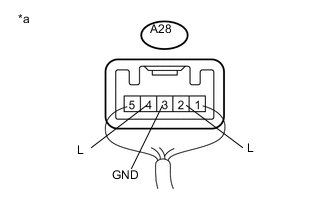
Text in Illustration *a Component with harness connected
(Stop Light Switch Assembly)
Measure the voltage according to the value(s) in the table below.
Standard Voltage Tester Connection Condition Specified Condition A28-2 (L) - A28-3 (GND) Power switch off, brake pedal not depressed Below 1 V Power switch off, brake pedal depressed 11 to 14 V A28-4 (L) - A28-3 (GND) Power switch ON, brake pedal not depressed 11 to 14 V Power switch ON, brake pedal depressed Below 1 V
NG
REPLACE STOP LIGHT SWITCH ASSEMBLY Click here
OK
-
-
CHECK HARNESS AND CONNECTOR (STOP LIGHT SWITCH ASSEMBLY - DRIVING SUPPORT ECU ASSEMBLY)
-
Disconnect the A28 stop light switch assembly connector.
-
Disconnect the H75 driving support ECU assembly connector.
-
Measure the resistance according to the value(s) in the table below.
Standard Resistance (Check for Open) Tester Connection Condition Specified Condition A28-4 (L) - H75-28 (ST1-) Always Below 1 Ω A28-2 (L) - H75-27 (STP-) Always Below 1 Ω Standard Resistance (Check for Short) Tester Connection Condition Specified Condition A28-4 (L) or H75-28 (ST1-) - Body ground Always 10 kΩ or higher A28-2 (L) or H75-27 (STP-) - Body ground Always 10 kΩ or higher -
Reconnect the H75 driving support ECU assembly connector.
-
Reconnect the A28 stop light switch assembly connector.
NG
REPAIR OR REPLACE HARNESS OR CONNECTOR
OK
-
-
CHECK HARNESS AND CONNECTOR (POWER MANAGEMENT CONTROL ECU - DRIVING SUPPORT ECU ASSEMBLY)
-
Disconnect the A33 power management control ECU connector.
-
Disconnect the H75 driving support ECU assembly connector.
-
Measure the resistance according to the value(s) in the table below.
Standard Resistance (Check for Open) Tester Connection Condition Specified Condition A33-7 (ST1-) - H75-28 (ST1-) Always Below 1 Ω A33-23 (STP) - H75-27 (STP-) Always Below 1 Ω Standard Resistance (Check for Short) Tester Connection Condition Specified Condition A33-7 (ST1-) or H75-28 (ST1-) - Body ground Always 10 kΩ or higher A33-23 (STP) or H75-27 (STP-) - Body ground Always 10 kΩ or higher -
Reconnect the H75 driving support ECU assembly connector.
-
Reconnect the A33 power management control ECU connector.
OK
REPLACE DRIVING SUPPORT ECU ASSEMBLY Click here
NG
REPAIR OR REPLACE HARNESS OR CONNECTOR
-