INTAKE MANIFOLD INSTALLATION
PROCEDURE
-
SET INTAKE MANIFOLD
-
Connect the fuel vapor feed hose to the intake manifold and slide the clip to secure it.
-
Engage the clamp and install the vacuum hose to the intake manifold.
-
Install the wire harness clamp bracket with the bolt.
- Torque:
- 10 N*m { 102 kgf*cm, 7 ft.*lbf }
-
Install a new gasket to the intake manifold.
-
Set the intake manifold to the cylinder head sub-assembly.
-
-
INSTALL FUEL DELIVERY PIPE
-
CONNECT FUEL TUBE SUB-ASSEMBLY
-
INSTALL INTAKE MANIFOLD
-
Temporarily install the intake manifold with the 6 bolts.
-
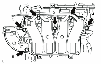
Tighten the 6 bolts in the order shown in the illustration.
- Torque:
- 28 N*m { 286 kgf*cm, 21 ft.*lbf }
-
Engage the 6 wire harness clamps.
-
Connect the heated oxygen sensor connector.
-
Connect the No. 2 ventilation hose to the intake manifold and slide the clip to secure it.
-
-
INSTALL MANIFOLD ABSOLUTE PRESSURE SENSOR
-
INSTALL INTAKE FLANGE
-
Install a new gasket to the intake manifold.
-
Type A:
-
Install the intake flange to the intake manifold with the 4 bolts.
- Torque:
- 10 N*m { 102 kgf*cm, 7 ft.*lbf }
-
-
Type B:
-
Install the intake flange to the intake manifold with the 3 bolts.
- Torque:
- 10 N*m { 102 kgf*cm, 7 ft.*lbf }
-
-
-
INSTALL FRONT OUTER COWL TOP PANEL SUB-ASSEMBLY (for LHD)
-
INSTALL FRONT OUTER COWL TOP PANEL SUB-ASSEMBLY (for RHD)
-
INSTALL WINDSHIELD WIPER MOTOR AND LINK ASSEMBLY
-
INSTALL THROTTLE BODY WITH MOTOR ASSEMBLY
-
CONNECT CABLE TO NEGATIVE AUXILIARY BATTERY TERMINAL
-
INSTALL LUGGAGE TRIM SERVICE HOLE COVER
-
INSPECT FOR FUEL LEAK