CYLINDER HEAD INSPECTION

PROCEDURE
-
INSPECT CYLINDER HEAD SUB-ASSEMBLY
-
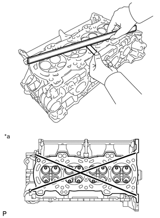
Using a precision straightedge and feeler gauge, measure the warpage of the contact surfaces where the cylinder head sub-assembly contacts the cylinder block sub-assembly and manifold.
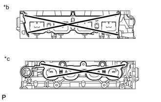
Maximum Warpage Item Specified Condition Cylinder head lower side 0.05 mm (0.00197 in.) Intake manifold side 0.10 mm (0.00394 in.) Exhaust manifold side 0.10 mm (0.00394 in.) Text in Illustration *a Cylinder Head Lower Side *b Intake Manifold Side *c Exhaust Manifold Side If the warpage is more than the maximum, replace the cylinder head sub-assembly.
-
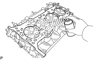
Using a dye penetrant, check the intake ports, exhaust ports and cylinder head sub-assembly surface for cracks.
If cracked, replace the cylinder head sub-assembly.
-
-
INSPECT COMPRESSION SPRING
Tech Tips
Type A and Type B can be distinguished by the shape of the compression spring.
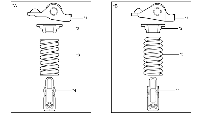
Text in Illustration *A Type A
(Compression Spring Shape: Straight)
*B Type B
(Compression Spring Shape: Tapered)
*1 No. 1 Valve Rocker Arm Sub-assembly *2 Valve Spring Retainer *3 Compression Spring *4 Valve Lash Adjuster Assembly
-
Type A:
-
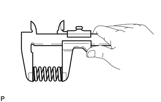
Using a vernier caliper, measure the free length of the compression spring.
Standard Free Length Wire Diameter Specified Condition 3.3 mm (0.130 in.) 49.0 to 51.0 mm (1.93 to 2.01 in.) 3.4 mm (0.134 in.) 47.2 to 49.2 mm (1.86 to 1.94 in.) If the free length is not as specified, replace the compression spring.
-
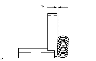
Text in Illustration *a Deviation Using a steel square, measure the deviation of the compression spring.
Maximum deviation 1.0 mm (0.0394 in.) Maximum angle 2° If the deviation is more than the maximum, replace the compression spring.
-
-
Type B:
-
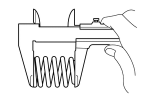
Using a vernier caliper, measure the free length of the compression spring.
Standard free length 47.38 mm (1.87 in.) If the free length is not as specified, replace the compression spring.
-
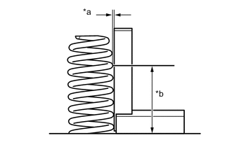
Text in Illustration *a Deviation *b 30 mm (1.18 in.) Using a steel square, measure the deviation of the compression spring at the position shown in the illustration.
Maximum deviation 1.0 mm (0.0394 in.) If the deviation is more than the maximum, replace the compression spring.
-
-
-
INSPECT INTAKE VALVE
-
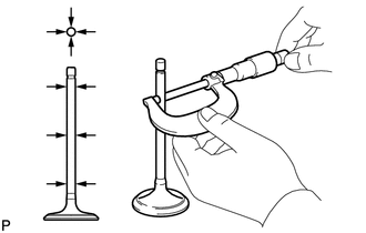
Using a micrometer, measure the diameter of the valve stem.
Standard valve stem diameter 5.470 to 5.485 mm (0.21535 to 0.21594 in.) -
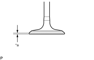
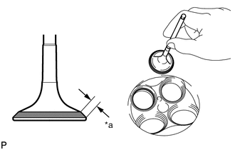
Text in Illustration *a Margin Thickness Using a vernier caliper, measure the valve head margin thickness.
Standard margin thickness 1.0 mm (0.0394 in.) Minimum margin thickness 0.50 mm (0.0197 in.) If the margin thickness is less than the minimum, replace the intake valve.
-
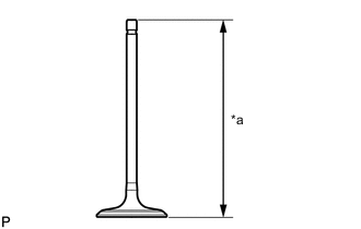
Text in Illustration *a Overall Length Using a vernier caliper, measure the overall length of the intake valve.
Standard overall length 103.92 mm (4.09 in.) Minimum overall length 103.42 mm (4.07 in.) If the overall length is less than the minimum, replace the intake valve.
-
-
INSPECT EXHAUST VALVE
-
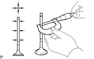
Using a micrometer, measure the diameter of the valve stem.
Standard valve stem diameter 5.465 to 5.480 mm (0.21516 to 0.21575 in.) -
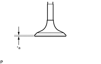
Text in Illustration *a Margin Thickness Using a vernier caliper, measure the valve head margin thickness.
Standard margin thickness 1.0 mm (0.0394 in.) Minimum margin thickness 0.50 mm (0.0197 in.) If the margin thickness is less than the minimum, replace the exhaust valve.
-
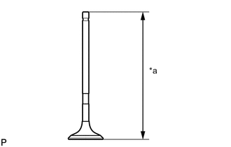
Text in Illustration *a Overall Length Using a vernier caliper, measure the overall length of the exhaust valve.
Standard overall length 112.91 mm (4.45 in.) Minimum overall length 112.41 mm (4.43 in.) If the overall length is less than the minimum, replace the exhaust valve.
-
-
INSPECT VALVE GUIDE BUSH OIL CLEARANCE
-
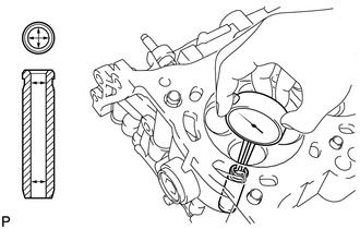
Using a caliper gauge, measure the inside diameter of the valve guide bush.
Standard Valve Guide bush inside diameter 5.510 to 5.530 mm (0.2169 to 0.2177 in.) -
Subtract the valve stem diameter measurement from the valve guide bush inside diameter measurement.
Standard Oil Clearance Item Specified Condition Intake 0.025 to 0.060 mm (0.000984 to 0.00236 in.) Exhaust 0.030 to 0.065 mm (0.00118 to 0.00256 in.) Maximum Oil Clearance Item Specified Condition Intake 0.08 mm (0.00315 in.) Exhaust 0.10 mm (0.00394 in.) If the oil clearance is more than the maximum, replace the valve and valve guide bush.
-
-
INSPECT INTAKE VALVE SEAT
-
Apply a light coat of Prussian blue to the valve face.
-
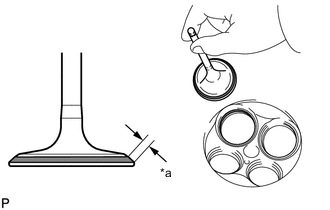
Text in Illustration *a Width Lightly press the valve face against the intake valve seat.
Tech Tips
Do not rotate the intake valve while pressing the it.
-
Check the valve face and seat according to the following procedure.
-
If Prussian blue appears 360° around the entire valve face, the valve face is concentric. If not, replace the intake valve.
-
If Prussian blue appears 360° around the entire valve seat, the guide and face are concentric. If not, resurface the intake valve seat.
-
Check that the seat contacts the middle of the valve face with the width between 1.1 and 1.5 mm (0.0433 and 0.0591 in.).
-
-
-
INSPECT EXHAUST VALVE SEAT
-
Apply a light coat of Prussian blue to the valve face.
-
Text in Illustration *a Width Lightly press the valve face against the exhaust valve seat.
Tech Tips
Do not rotate the exhaust valve while pressing it.
-
Check the valve face and seat according to the following procedure.
-
If Prussian blue appears 360° around the entire valve face, the valve face is concentric. If not, replace the exhaust valve.
-
If Prussian blue appears 360° around the entire valve seat, the guide and face are concentric. If not, resurface the exhaust valve seat.
-
Check that the seat contacts the middle of the valve face with the width between 1.1 and 1.5 mm (0.0433 and 0.0591 in.).
-
-
-
INSPECT CAMSHAFT OIL CLEARANCE
Note
Do not turn the camshafts.
-
Clean the No. 1 camshaft bearing cap, No. 2 camshaft bearing cap, 3 No. 3 camshaft bearing caps, camshaft housing sub-assembly and camshaft journals.
-
Place the camshaft and No. 2 camshaft on the camshaft housing sub-assembly.
-
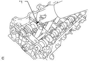
Text in Illustration *1 Plastigage Lay a strip of Plastigage across each of the camshaft journals.
-
Install the No. 1 camshaft bearing cap, No. 2 camshaft bearing cap and 3 No. 3 camshaft bearing caps Click here.
-
Install the camshaft housing sub-assembly Click here.
-
Remove the No. 1 camshaft bearing cap, No. 2 camshaft bearing cap and 3 No. 3 camshaft bearing caps Click here.
-
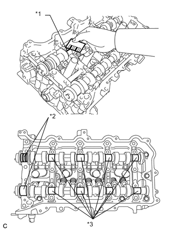
Text in Illustration *1 Plastigage *2 No. 1 Journal *3 Other Journal Measure the Plastigage at its widest point.
Standard Oil Clearance Item Specified Condition Intake No. 1 journal 0.035 to 0.072 mm (0.00138 to 0.00283 in.) Exhaust No. 1 journal 0.005 to 0.054 mm (0.000197 to 0.00213 in.) Other journal 0.025 to 0.062 mm (0.000984 to 0.00244 in.) Maximum Oil Clearance Item Specified Condition Intake No. 1 journal 0.085 mm (0.00335 in.) Exhaust No. 1 journal 0.085 mm (0.00335 in.) Other journal 0.085 mm (0.00335 in.) If the oil clearance is more than the maximum, replace the camshaft. If necessary, replace the camshaft housing sub-assembly.
-
-
INSPECT CAMSHAFT THRUST CLEARANCE
-
Clean the No. 1 camshaft bearing cap, No. 2 camshaft bearing cap, 3 No. 3 camshaft bearing caps, camshaft housing sub-assembly and camshaft journals.
-
Place the camshaft and No. 2 camshaft on the camshaft housing sub-assembly.
-
Install the No. 1 camshaft bearing cap, No. 2 camshaft bearing cap and 3 No. 3 camshaft bearing caps Click here.
-
Install the camshaft housing sub-assembly Click here.
-
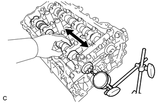
Using a dial indicator, measure the thrust clearance while moving the camshaft back and forth.
Standard Thrust Clearance Item Specified Condition Intake 0.060 to 0.155 mm (0.00236 to 0.00610 in.) Exhaust 0.060 to 0.155 mm (0.00236 to 0.00610 in.) Maximum Thrust Clearance Item Specified Condition Intake 0.170 mm (0.00669 in.) Exhaust 0.170 mm (0.00669 in.) If the thrust clearance is more than the maximum, replace the camshaft housing sub-assembly. If the thrust surface is damaged, replace the camshaft.
-