ENGINE UNIT INSTALLATION

CAUTION / NOTICE / HINT
Tech Tips
Perform "Inspection After Repair" after replacing the engine assembly Click here.
PROCEDURE
-
INSTALL IGNITION COIL ASSEMBLY
-
INSTALL SENSOR WIRE
-
Install the sensor wire with the bolt.
- Torque:
- 21 N*m { 214 kgf*cm, 15 ft.*lbf }
-
Connect the knock control sensor connector.
-
-
INSTALL FUEL DELIVERY PIPE
-
INSTALL INTAKE MANIFOLD
-
Install a new gasket to the intake manifold.
-
Set the intake manifold on the engine assembly.
-
Temporarily install the intake manifold with the 6 bolts.
-
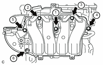
Tighten the 6 bolts in the order shown in the illustration.
- Torque:
- 28 N*m { 286 kgf*cm, 21 ft.*lbf }
-
Connect the No. 2 ventilation hose to the intake manifold.
-
-
INSTALL NO. 1 COMPRESSOR MOUNTING BRACKET
-
Install the No. 1 compressor mounting bracket with the 4 bolts.
- Torque:
- 25 N*m { 255 kgf*cm, 18 ft.*lbf }
-
-
INSTALL WATER INLET HOUSING
-
Using an E5 "TORX" socket wrench, install the stud bolt to the water inlet housing.
- Torque:
- 8.0 N*m { 82 kgf*cm, 71 in.*lbf }
-
Using an E8 "TORX" socket wrench, install the stud bolt to the cylinder block sub-assembly.
- Torque:
- 15 N*m { 153 kgf*cm, 11 ft.*lbf }
-
Install a new gasket.
-
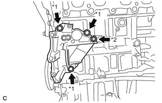
Text in Illustration *1 Bolt *2 Nut Install the water inlet housing with the 3 bolts and nut.
- Torque:
- 43 N*m { 438 kgf*cm, 32 ft.*lbf }
-
Install the harness clamp bracket to the water inlet housing with the bolt.
- Torque:
- 10 N*m { 102 kgf*cm, 7 ft.*lbf }
-
Install the harness clamp bracket to the cylinder block sub-assembly with the bolt.
- Torque:
- 8.0 N*m { 82 kgf*cm, 71 in.*lbf }
-
-
INSTALL WATER INLET SUB-ASSEMBLY
-
Install a new gasket and the water inlet sub-assembly with the 2 bolts.
- Torque:
- 10 N*m { 102 kgf*cm, 7 ft.*lbf }
-
-
INSTALL ENGINE WATER PUMP ASSEMBLY
-
Install a new gasket and the engine water pump assembly with the 5 bolts.
- Torque:
- 21 N*m { 214 kgf*cm, 15 ft.*lbf }
-
-
INSTALL NO. 1 WATER BY-PASS PIPE
-
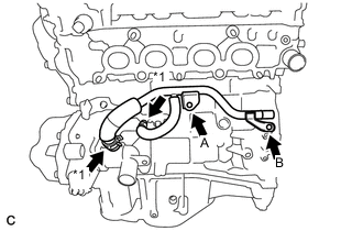
Text in Illustration *1 Clamp Install the No. 1 water by-pass pipe with the 2 bolts.
- Torque:
- Bolt A
- 21 N*m { 214 kgf*cm, 15 ft.*lbf }
- Bolt B
- 10 N*m { 102 kgf*cm, 7 ft.*lbf }
-
Connect the No. 4 water by-pass hose and No. 6 water by-pass hose with the 2 clamps.
-
-
INSTALL NO. 3 WATER BY-PASS PIPE
-
Install the No. 3 water by-pass pipe with the 2 bolts.
- Torque:
- 21 N*m { 214 kgf*cm, 15 ft.*lbf }
-
Connect the No. 5 water by-pass hose with the clamp.
-
-
INSTALL EXHAUST MANIFOLD CONVERTER SUB-ASSEMBLY
-
INSTALL MANIFOLD STAY
-
INSTALL NO. 2 MANIFOLD STAY
-
INSTALL NO. 1 EXHAUST MANIFOLD HEAT INSULATOR
-
INSTALL NO. 1 WATER BY-PASS HOSE
-
Connect the No. 1 water by-pass hose with the clamp.
-
-
INSTALL THROTTLE WITH MOTOR BODY ASSEMBLY
-
INSTALL ENGINE OIL LEVEL DIPSTICK GUIDE
-
Apply a light coat of engine oil to a new O-ring.
-
Install the O-ring to the engine oil level dipstick guide.
-
Install the engine oil level dipstick guide with the bolt.
- Torque:
- 10 N*m { 102 kgf*cm, 7 ft.*lbf }
-
Install the engine oil level dipstick.
-
-
INSTALL ENGINE HANGERS
-
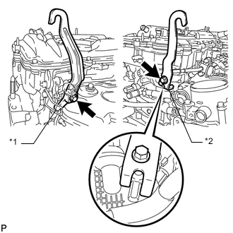
Text in Illustration *1 No. 1 Engine Hanger *2 No. 2 Engine Hanger Install the No. 1 engine hanger and No. 2 engine hanger with the 2 bolts as shown in the illustration.
Part No. Item Part No. No. 1 Engine Hanger 12281-36020 No. 2 Engine Hanger 12282-36021 Bolt 91552-81025 or 91552-81040 - Torque:
- 43 N*m { 438 kgf*cm, 32 ft.*lbf }
-