CAUTION / NOTICE / HINT
Perform "Inspection After Repair" after replacing the camshaft, No. 2 camshaft or camshaft timing gear assembly (Click here).
PROCEDURE
- Click here
INSPECT CAMSHAFT TIMING GEAR ASSEMBLY
- Click here
INSTALL NO. 2 CAMSHAFT BEARING
- Click here
INSTALL NO. 1 CAMSHAFT BEARING
- Click here
INSTALL OIL CONTROL VALVE FILTER
- Click here
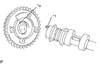
INSTALL CAMSHAFT TIMING SPROCKET
-
Secure the No. 2 camshaft in a vise by clamping the hexagonal part using aluminum plates.
Note:Do not damage the No. 2 camshaft by tightening the vise excessively.
-
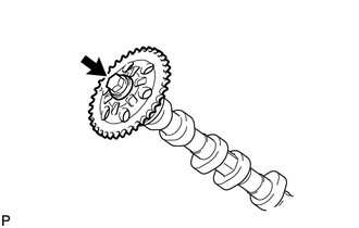
Install the camshaft timing sprocket to the No. 2 camshaft with the bolt.
85 N*m 867 kgf*cm 63 ft.*lbf Note:Do not damage the No. 2 camshaft or camshaft timing sprocket.
-
- Click here
SET NO. 1 CYLINDER TO TDC/COMPRESSION
-
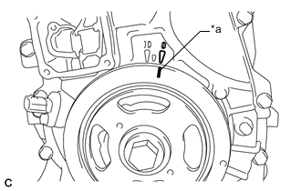
Turn the crankshaft pulley until its timing notch (groove) and the timing mark "0" of the timing chain cover sub-assembly are aligned.
Table 1. Text in Illustration *a Timing Notch
-
- Click here
INSTALL NO. 2 CAMSHAFT
-
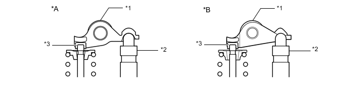
Make sure that the No. 1 valve rocker arm sub-assemblies are installed as shown in the illustration.
Table 2. Text in Illustration *A Type A *B Type B *1 No. 1 Valve Rocker Arm Sub-assembly *2 Valve Lash Adjuster Assembly *3 Valve Stem Cap - - -
Clean the camshaft journals.
-
Apply a light coat of engine oil to the camshaft journals, camshaft housing sub-assembly and bearing caps.
-
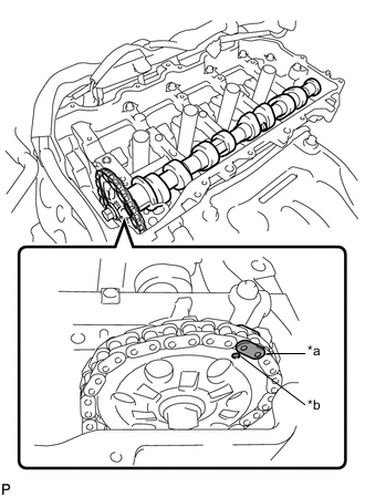
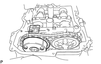
Hold up the chain sub-assembly and align the timing mark and the paint mark, and install the No. 2 camshaft.
Table 3. Text in Illustration *a Paint Mark *b Timing mark Tip:Perform "Inspection After Repair" after replacing the No. 2 camshaft (Click here).
-
- Click here
INSTALL CAMSHAFT
-
Make sure that the No. 1 valve rocker arm sub-assemblies are installed as shown in the illustration.
Table 4. Text in Illustration *A Type A *B Type B *1 No. 1 Valve Rocker Arm Sub-assembly *2 Valve Lash Adjuster Assembly *3 Valve Stem Cap - - -
Clean the camshaft journals.
-
Apply a light coat of engine oil to the camshaft journals, camshaft housing sub-assembly and bearing caps.
-
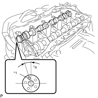
Install the camshaft to the camshaft housing sub-assembly as shown in the illustration.
Table 5. Text in Illustration *1 Knock Pin *a Approximately 17° Tip:Perform "Inspection After Repair" after replacing the camshaft (Click here).
-
- Click here
INSTALL CAMSHAFT BEARING CAP
-
Confirm the marks and numbers on the 3 No. 3 camshaft bearing caps, No. 2 camshaft bearing cap, No. 1 camshaft bearing cap and place them in their proper positions and directions.
-
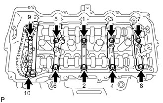
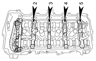
Using several steps, uniformly tighten the 10 bolts in the sequence shown in the illustration.
27 N*m 275 kgf*cm 20 ft.*lbf -
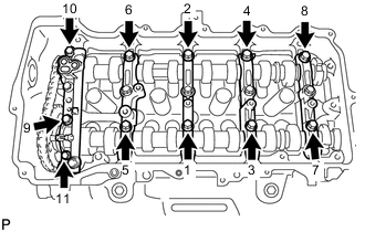
Using several steps, uniformly tighten the 11 bolts in the sequence shown in the illustration.
16 N*m 163 kgf*cm 12 ft.*lbf -
Check the torque of each bolt again.
-
- Click here
INSTALL CAMSHAFT TIMING GEAR ASSEMBLY
-
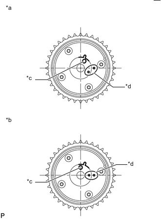
Check the camshaft timing gear assembly position.
Table 6. Text in Illustration *a Advance Position *b Retard Position *c Knock Pin Hole *d Alignment Mark Note:
-
If the camshaft timing gear assembly is set to the advanced position, do not let the camshaft timing gear assembly rotate clockwise during installation.
-
If the camshaft timing gear assembly has rotated to the most retarded position, make sure to release the lock pin and set the camshaft timing gear assembly to the most advanced position before tightening the camshaft timing gear assembly.
-
-
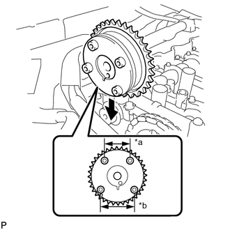
Install the camshaft timing gear assembly as shown in the illustration.
Table 7. Text in Illustration *a Narrow *b Wide -
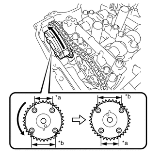
Turn the camshaft timing gear assembly approximately 180° counterclockwise.
Table 8. Text in Illustration *a Narrow *b Wide -
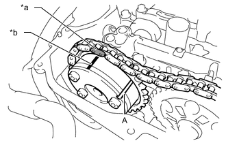
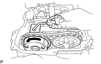
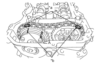
Align the paint mark with the timing mark and install the chain sub-assembly to the camshaft timing gear assembly.
Table 9. Text in Illustration *a Paint Mark *b Timing mark Tip:"A" is not a timing mark.
-
Align and insert the knock pin of the camshaft with the pin hole of the camshaft timing gear assembly.
Table 10. Text in Illustration *1 Knock Pin *a Knock Pin Hole -
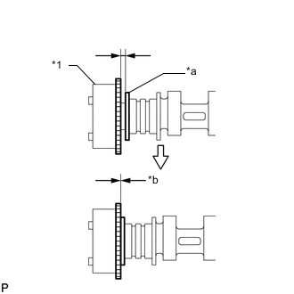
Check that there is no clearance between the camshaft timing gear assembly and camshaft flange.
Table 11. Text in Illustration *1 Camshaft Timing Gear Assembly *a Camshaft Flange *b No Clearance -
Secure the camshaft in place by hand, and then install the installation bolt of the camshaft timing gear assembly by hand.
Note:Do not use any tools to install the bolt. If the bolt is installed using a tool, the lock pin will be damaged.
-
If the lock pin has not been released, release it.
-
After cleaning and degreasing the intake side VVT oil hole on the No. 1 camshaft bearing cap, completely seal the oil hole with adhesive tape or equivalent as shown in the illustration to prevent air from leaking.
Table 12. Text in Illustration *a Make a Hole *b Adhesive Tape Sealing Area Note:Be sure to seal the oil hole completely because air leaks due to insufficient sealing will prevent the lock pin from being released.
-
Make a hole in the adhesive tape covering the oil hole as shown in the illustration. (Procedure A)
-
Apply approximately 200 kPa (2.0 kgf/ cm2, 29 psi) of air pressure to the hole made in procedure A to release the lock pin.
Note:
-
If air leaks out, reattach the adhesive tape.
-
Cover the oil hole with a piece of cloth when applying air pressure to prevent oil from spraying.
-
-
Forcibly turn the camshaft timing gear assembly in the advance direction (counterclockwise).
Tip:
-
Depending on the air pressure applied, the camshaft timing gear assembly may turn in the advance direction without assistance by hand.
-
If enough air pressure cannot be applied because of air leakage from the port, releasing the lock pin may be difficult.
-
-
Remove the adhesive tape from the No. 1 camshaft bearing cap.
-
-
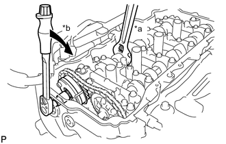
Using a wrench to hold the hexagonal portion of the camshaft, install the bolt.
Table 13. Text in Illustration *a Hold *b Turn 85 N*m 867 kgf*cm 63 ft.*lbf Note:Be careful not to damage the cylinder head sub-assembly or spark plug tube with the wrench.
-
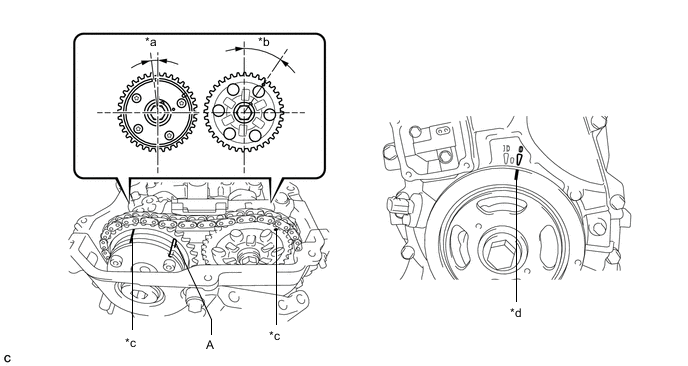
Check that both timing marks on the camshaft timing gear assembly and camshaft timing sprocket are facing upward as shown in the illustration.
Table 14. Text in Illustration *a Paint Mark *b Timing Mark Tip:
-
"A" is not a timing mark.
-
Perform "Inspection After Repair" after replacing the camshaft timing gear assembly (Click here).
-
-
- Click here
ADD ENGINE OIL
- Click here
INSTALL TIMING CHAIN GUIDE
- Click here
INSTALL NO. 1 CHAIN TENSIONER ASSEMBLY
-
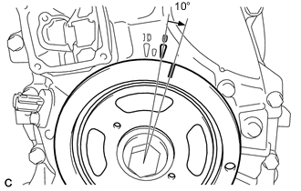
Turn the crankshaft pulley approximately 10° clockwise.
-
Install a new gasket and the No. 1 chain tensioner assembly with the 2 bolts.
10 N*m 102 kgf*cm 7 ft.*lbf Note:Make sure not to drop the gasket inside the timing chain cover sub-assembly.
-
Remove the pin from the stopper plate.
-
- Click here
SET NO. 1 CYLINDER TO TDC/COMPRESSION
-
Turn the crankshaft pulley until its timing notch (groove) and the timing mark "0" of the timing chain cover are aligned.
Table 15. Text in Illustration *a Approximately 7° *b Approximately 32° *c Timing Mark *d Timing Notch -
Check that both timing marks on the camshaft timing gear assembly and camshaft timing sprocket are facing upward as shown in the illustration. If not, turn the crankshaft 1 revolution (360°) to align the timing marks as shown in the illustration.
Tip:"A" is not a timing mark.
-
- Click here
INSTALL TIMING CHAIN COVER PLATE
-
Install a new gasket and the timing chain cover plate with the 4 bolts.
10 N*m 102 kgf*cm 7 ft.*lbf
-
- Click here
INSTALL OIL PUMP RELIEF VALVE PLUG
- Click here
INSTALL CYLINDER HEAD COVER SUB-ASSEMBLY
- Click here
INSTALL IGNITION COIL ASSEMBLY
- Click here
CONNECT ENGINE WIRE
-
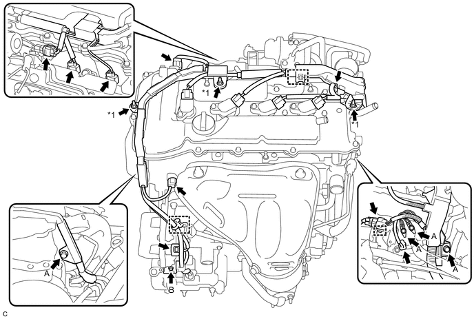
Install the engine wire to the engine with the 5 bolts and 3 nuts.
Table 16. Text in Illustration *1 Nut - - Bolt A 8.0 N*m 82 kgf*cm 71 in.*lbf Bolt B 10 N*m 102 kgf*cm 7 ft.*lbf Nut 8.0 N*m 82 kgf*cm 71 in.*lbf -
Connect the 9 connectors and 3 harness clamps.
-
- Click here
INSTALL NO. 2 ENGINE ROOM RELAY BLOCK
-
Install the No. 2 engine room relay block with the bolt and 2 clamps.
8.0 N*m 82 kgf*cm 71 in.*lbf -
Install the front fender liner RH with the screw.
-
- Click here
INSTALL INVERTER RESERVE TANK ASSEMBLY
-
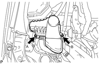
Temporarily install the inverter reserve tank assembly with the 2 bolts.
-
Tighten the 2 bolts in the order bolt A and bolt B.
10 N*m 102 kgf*cm 7 ft.*lbf
-
- Click here
INSTALL ENGINE MOVING CONTROL ROD BRACKET
- Click here
INSTALL EARTH WIRE
- Click here
INSTALL NO. 2 ENGINE MOUNTING STAY RH
- Click here
INSTALL AIR CLEANER CASE SUB-ASSEMBLY
- Click here
INSTALL AIR CLEANER FILTER ELEMENT
- Click here
INSTALL AIR CLEANER CAP SUB-ASSEMBLY
- Click here
INSTALL INLET AIR CLEANER ASSEMBLY
- Click here
INSPECT FOR OIL LEAK
- Click here
INSTALL FRONT FENDER APRON SEAL RH
- Click here
INSTALL ENGINE UNDER COVER RH (w/o Front Lower Bumper Absorber)
- Click here
INSTALL ENGINE UNDER COVER RH (w/ Front Lower Bumper Absorber)
-
Install the engine under cover RH with the 2 bolts, 2 screws and 3 clips.
-
- Click here
INSTALL FRONT WHEEL OPENING EXTENSION PAD RH
- Click here
INSTALL NO. 1 ENGINE COVER SUB-ASSEMBLY
- Click here
INSTALL COOL AIR INTAKE DUCT SEAL
- Click here
INSTALL FRONT WHEEL RH
103 N*m 1049 kgf*cm 76 ft.*lbf