CAMSHAFT REMOVAL
PROCEDURE
-
REMOVE FRONT WHEEL RH
-
REMOVE FRONT WHEEL OPENING EXTENSION PAD RH
-
REMOVE ENGINE UNDER COVER RH (w/o Front Lower Bumper Absorber)
-
REMOVE ENGINE UNDER COVER RH (w/ Front Lower Bumper Absorber)
-
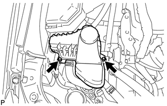
Remove the 2 bolts, 2 screws, 3 clips and engine under cover RH.
-
-
REMOVE FRONT FENDER APRON SEAL RH
-
REMOVE NO. 1 ENGINE COVER SUB-ASSEMBLY
-
REMOVE COOL AIR INTAKE DUCT SEAL
-
REMOVE INLET AIR CLEANER ASSEMBLY
-
REMOVE AIR CLEANER CAP SUB-ASSEMBLY
-
REMOVE AIR CLEANER FILTER ELEMENT
-
REMOVE AIR CLEANER CASE SUB-ASSEMBLY
-
REMOVE NO. 2 ENGINE MOUNTING STAY RH
-
DISCONNECT EARTH WIRE
-
REMOVE ENGINE MOVING CONTROL ROD BRACKET
-
SEPARATE INVERTER RESERVE TANK ASSEMBLY
-
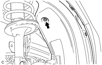
Remove the 2 bolts and separate the inverter reserve tank assembly.
-
-
SEPARATE NO. 2 ENGINE ROOM RELAY BLOCK
-
Remove the screw and separate the front fender liner RH.
-
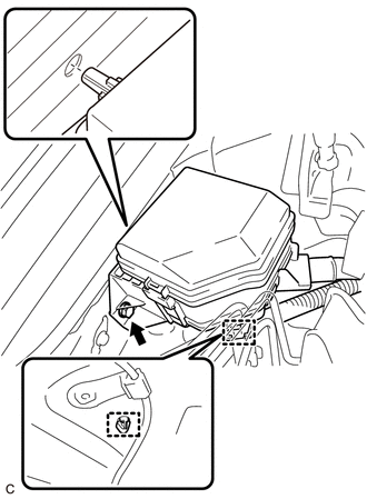
Remove the bolt, separate the 2 clamps and No. 2 engine room relay block.
-
-
DISCONNECT ENGINE WIRE
-
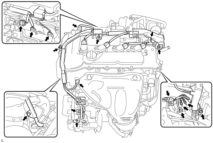
Disconnect the 9 connectors and 3 harness clamps.
-
Remove the 5 bolts and 3 nuts and disconnect the engine wire from the engine.
-
-
REMOVE IGNITION COIL ASSEMBLY
-
REMOVE CYLINDER HEAD COVER SUB-ASSEMBLY
-
SET NO. 1 CYLINDER TO TDC/COMPRESSION
-
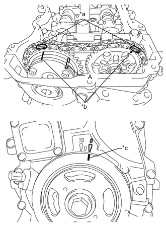
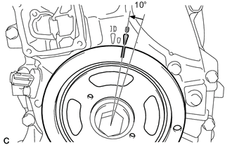
Text in Illustration *a Paint Mark *b Timing Mark *c Timing Notch Turn the crankshaft pulley until its timing notch (groove) and the timing mark "0" of the timing chain cover sub-assembly are aligned.
-
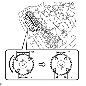
Check that both timing marks on the camshaft timing gear assembly and camshaft timing sprocket are facing upward as shown in the illustration. If not, turn the crankshaft 1 revolution (360°) to align the timing marks as shown in the illustration.
Tech Tips
"A" is not a timing mark.
-
Place paint marks on the chain sub-assembly in alignment with the timing marks on the camshaft timing gear assembly and camshaft timing sprocket.
-
-
REMOVE TIMING CHAIN COVER PLATE
-
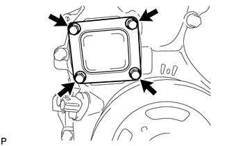
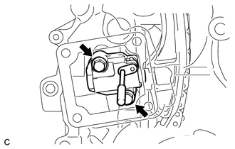
Remove the 4 bolts, timing chain cover plate and gasket.
-
-
REMOVE NO. 1 CHAIN TENSIONER ASSEMBLY
-
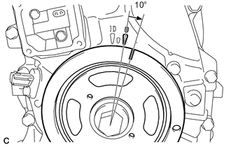
Turn the crankshaft pulley approximately 10° clockwise.
-

Turn the crankshaft pulley approximately 10° counterclockwise.
-
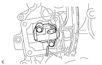
Text in Illustration *1 Pin Align the holes of the stopper plate and No. 1 chain tensioner assembly, and insert a pin into the stopper plate hole to lock the No. 1 chain tensioner assembly.
-

Turn the crankshaft pulley approximately 10° clockwise.
-
Remove the 2 bolts, No. 1 chain tensioner assembly and gasket.
Note
Make sure not to drop the gasket inside the timing chain cover sub-assembly.
-
Turn the crankshaft pulley approximately 10° counterclockwise.
-
-
REMOVE TIMING CHAIN GUIDE
-
REMOVE OIL PUMP RELIEF VALVE PLUG
-
REMOVE CAMSHAFT TIMING GEAR ASSEMBLY
-
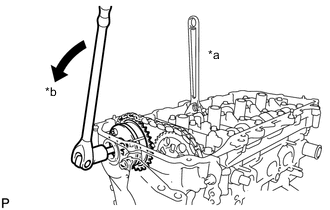
Text in Illustration *a Hold *b Turn Hold the hexagonal portion of the camshaft with a wrench and remove the bolt from the camshaft.
Note
Be careful not to damage the cylinder head sub-assembly or spark plug tube with the wrench.
-
Separate the camshaft timing gear assembly from the camshaft.
-
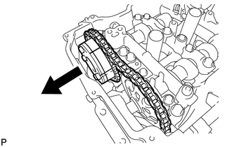
Text in Illustration *a Narrow *b Wide Remove the chain sub-assembly from the camshaft timing gear assembly, and turn the camshaft timing gear assembly approximately 180°.
-
Remove the camshaft timing gear assembly.
Note
Do not disassemble the camshaft timing gear assembly.
-
-
REMOVE CAMSHAFT BEARING CAP
-
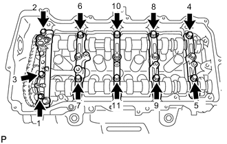
Using several steps, remove the 11 bolts in the sequence shown in the illustration.
-
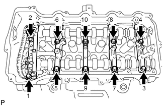
Using several steps, remove the 10 bolts in the sequence shown in the illustration.
-
Remove the No. 1 camshaft bearing cap, No. 2 camshaft bearing cap and 3 No. 3 camshaft bearing caps.
Tech Tips
Arrange the removed parts in the correct order.
-
-
REMOVE CAMSHAFT
-
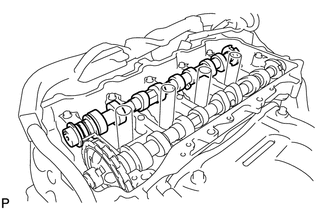
Remove the camshaft from the camshaft housing sub-assembly.
-
-
REMOVE NO. 2 CAMSHAFT
-
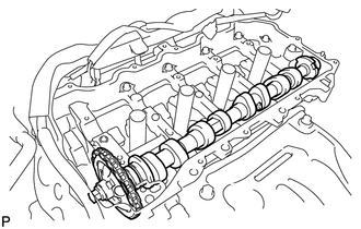
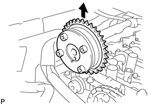
Hold up the chain sub-assembly and remove the No. 2 camshaft from the camshaft housing sub-assembly.
-
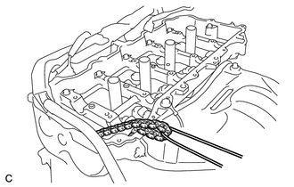
Suspend the chain sub-assembly with a string or equivalent as shown in the illustration.
Note
Be careful not to drop the chain sub-assembly inside the timing chain cover sub-assembly.
-
-
REMOVE CAMSHAFT TIMING SPROCKET
-
Secure the No. 2 camshaft in a vise by clamping the hexagonal part using aluminum plates.
Note
Do not damage the No. 2 camshaft by tightening the vise excessively.
-
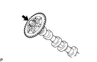
Remove the bolt and camshaft timing sprocket.
Note
Do not damage the No. 2 camshaft or camshaft timing sprocket.
-
-
REMOVE OIL CONTROL VALVE FILTER
-
REMOVE NO. 1 CAMSHAFT BEARING
-
REMOVE NO. 2 CAMSHAFT BEARING