ENGINE ON-VEHICLE INSPECTION

PROCEDURE
-
INSPECT COOLANT (for Engine)
-
INSPECT ENGINE OIL
-
INSPECT AUXILIARY BATTERY
-
INSPECT AIR CLEANER FILTER ELEMENT SUB-ASSEMBLY
-
Remove the air cleaner cap sub-assembly.
-
Remove the air cleaner filter element sub-assembly.
-
Visually check that the air cleaner filter element sub-assembly is not excessively damaged or oily.
If necessary, replace the air cleaner filter element sub-assembly.
-
Install the air cleaner filter element sub-assembly.
-
Install the air cleaner cap sub-assembly.
-
-
INSPECT SPARK PLUG
-
INSPECT VALVE LASH ADJUSTER ASSEMBLY NOISE
-
Put the engine in inspection mode Click here.
-
Rev up the engine several times. Check that the engine does not emit unusual noises. If unusual noises occur, warm up the engine and idle it for over 30 minutes. Then, perform the inspection above again. If any defects or problems are found during the inspection above, perform a valve lash adjuster assembly inspection Click here.
-
-
INSPECT IGNITION TIMING
-
Put the engine in inspection mode Click here.
-
Warm up and stop the engine.
-
When using the GTS:
Check the ignition timing.
-
Connect the GTS to the DLC3.
-
Put the engine in inspection mode Click here.
-
Enter the following menus: Powertrain / Engine and ECT / Data List / IGN Advance.
Standard ignition timing 5 to 20 degrees BTDC Note
-
Check the ignition timing with the cooling fans off.
-
Turn all electrical systems and the A/C off.
-
When checking the ignition timing, the shift lever should be in P.
Tech Tips
Refer to the GTS operator's manual for further details.
If the ignition timing is not as specified, check the valve timing.
-
-
Check that the ignition timing advances immediately when the engine speed is increased.
-
Enter the following menus: Powertrain / Engine and ECT / Active Test / Connect the TC and TE1 / ON.
-
Monitor IGN Advance of the Data List.
Standard ignition timing 8 to 12 degrees BTDC Note
-
Check the ignition timing with the cooling fans off.
-
Turn all electrical systems and the A/C off.
-
When checking the ignition timing, the shift lever should be in P.
Tech Tips
Refer to the GTS operator's manual for further details.
If the ignition timing is not as specified, check the valve timing.
-
-
Enter the following menus: Connect the TC and TE1 / OFF.
-
Turn the power switch off.
-
Turn the GTS off.
-
Disconnect the GTS from the DLC3.
-
-
When not using the GTS:
-
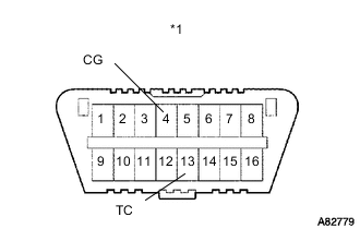
Text in Illustration *1 DLC3 Using SST, connect terminals 13 (TC) and 4 (CG) of the DLC3.
- SST
- 09843-18040
Note
Confirm the terminals before connecting them. Connecting the wrong terminals may result in damage to electrical components.
-
Remove the No. 1 engine cover sub-assembly.
-
Pull out the wire harness.
Note
After checking, wrap the wire harness with tape.
-
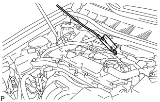
Connect the clip of the timing light to the wire harness.
Note
Use a timing light that detects the primary signal.
-
Inspect the ignition timing at idle.
Standard ignition timing 8 to 12 degrees BTDC Note
-
Check the ignition timing with the cooling fans off.
-
Turn all electrical systems and the A/C off.
-
When checking the ignition timing, the shift lever should be in P.
If the ignition timing is not as specified, check the valve timing.
-
-
Disconnect terminals 13 (TC) and 4 (CG) of the DLC3.
-
Inspect the ignition timing at idle.
Standard ignition timing 5 to 20 degrees BTDC Note
-
Check the ignition timing with the cooling fans off.
-
Turn all electrical systems and the A/C off.
-
When checking the ignition timing, the shift lever should be in P.
If the ignition timing is not as specified, check the valve timing.
-
-
Confirm that the ignition timing advances when the engine rpm is increased.
-
Remove the timing light.
-
Install the No. 1 engine cover sub-assembly.
-
-
-
INSPECT ENGINE IDLE SPEED
-
Put the engine in inspection mode Click here.
-
Warm up and stop the engine.
-
When using the GTS:
-
Connect the GTS to the DLC3.
-
Put the engine in inspection mode Click here.
-
Enter the following menus: Powertrain / Engine and ECT / Data List / Engine Speed.
Tech Tips
Refer to the GTS operator's manual for further details.
-
Inspect the engine idle speed.
Standard idle speed 900 to 1050 rpm Note
-
Turn all electrical systems and the A/C off.
-
Inspect the engine idle speed with the cooling fans off.
-
When checking the engine idle speed, the shift lever should be in P.
-
-
Turn the power switch off.
-
Turn the GTS off.
-
Disconnect the GTS from the DLC3.
-
-
When not using the GTS:
-
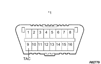
Text in Illustration *1 DLC3 Using SST, connect a tachometer tester probe to terminal 9 (TAC) of the DLC3.
- SST
- 09843-18030
-
Put the engine in inspection mode Click here.
-
Inspect the engine idle speed.
Standard idle speed 900 to 1050 rpm Note
-
Turn all electrical systems and the A/C off.
-
Inspect the idle speed with the cooling fans off.
-
When checking the engine idle speed, the shift lever should be in P.
-
-
Disconnect the tachometer probe from the DLC3.
-
-
-
INSPECT COMPRESSION
-
Put the engine in inspection mode Click here.
-
Warm up and stop the engine.
-
Remove the 4 spark plugs Click here.
Note
If the ignition coil assembly connector is disconnected because a DTC is detected in inspection, always reconnect it.
-
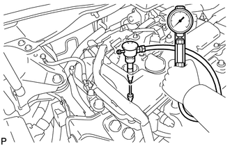
Inspect the cylinder compression pressure.
-
Insert a compression gauge into the spark plug hole.
-
Connect the GTS to the DLC3.
-
Turn the power switch on (IG).
-
Turn the GTS on.
Note
Check the HV battery voltage in the data list to ensure that the battery is fully charged.
-
Enter the following menus: Powertrain / Hybrid Control / Active Test / Compression Test / ON.
-
Depress and hold the brake pedal, and turn the power switch on (READY).
Note
The measurement must be done as quickly as possible.
Tech Tips
Noise may be emitted from the transmission. However, this is not a malfunction.
Standard compression pressure 1100 kPa (11.2 kgf/cm2, 160 psi) Minimum pressure 750 kPa (7.6kgf/cm2, 109 psi) Pressure difference between each cylinder 100 kPa (1.0 kgf/cm2, 15 psi) Note
-
Inspect the other cylinders in the same way.
-
Measure the compression as quickly as possible.
-
-
If the cylinder compression is low, pour a small amount of engine oil into the cylinder through the spark plug hole, then inspect it again.
Tech Tips
-
If adding oil increases the compression, the piston rings and/or cylinder bore may be worn or damaged.
-
If the pressure stays low, a valve may be stuck or seated improperly, or there may be leaks from the gasket.
-
-
-
Install the 4 spark plugs Click here.
Note
After performing all the steps, be sure to clear any DTCs stored in memory.
-
-
INSPECT CO/HC
Tech Tips
This check determines whether or not the idle CO / HC complies with regulations.
-
Put the engine in inspection mode Click here.
-
Warm up the engine.
-
Run the engine at 2500 rpm for approximately 180 seconds.
-
Insert a CO/HC meter testing probe at least 40 cm (1.31 ft.) into the tailpipe while idling.
-
Check the CO/HC concentration at idle and when the engine is running at 2500 rpm.
Tech Tips
-
When doing a 2 mode (with the engine idling/ running at 2500 rpm) test, the measurement procedures are determined by applicable local regulations.
-
If the CO/HC concentration does not comply with the regulations, troubleshoot in the order given below.
-
Check the DTCs Click here.
-
See the table below for possible causes, then inspect the applicable parts and repair them if necessary.
CO HC Problem Possible Cause Normal High Rough idle
-
Faulty ignition:
-
Incorrect timing
-
Fouled, shorted or improperly gapped plugs
-
Incorrect valve clearance
-
Leaks from intake and exhaust valves
-
Leaks from cylinders
Low High Rough idle (Fluctuating HC reading)
-
Vacuum leaks:
-
PCV hoses
-
Intake manifold
-
Throttle body
-
Lean mixture causing misfire
High High Rough idle (Black smoke from exhaust)
-
Restricted air cleaner filter element
-
Plugged PCV valve
-
Faulty EFI systems:
-
Faulty pressure regulator
-
Faulty engine coolant temperature sensor
-
Faulty mass air flow meter
-
Faulty ECM
-
Faulty injectors
-
Throttle body
-
-
-