CYLINDER BLOCK REASSEMBLY
Info Added 2017-08-02 ![]()
CAUTION / NOTICE / HINT
Tech Tips
Perform "Inspection After Repair" after replacing the piston or piston ring Click here.
PROCEDURE
-
INSTALL STUD BOLT
Note
If a stud bolt is deformed or the threads are damaged, replace it.
-
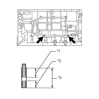
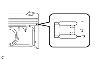
*1 20 mm (0.787 in.) *2 13 mm (0.512 in.) *3 35 mm (1.38 in.) Using an E8 "TORX" socket wrench, install the 2 stud bolts.
- Torque:
- 6.5 N*m { 66 kgf*cm, 58 in.*lbf }
-
-
INSTALL NO. 2 OIL NOZZLE SUB-ASSEMBLY
-
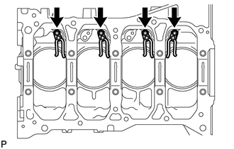
Using a 5 mm hexagon wrench, install the 4 No. 2 oil nozzles sub-assemblies with the 4 bolts.
- Torque:
- 10 N*m { 102 kgf*cm, 7 ft.*lbf }
-
-
INSTALL NO. 1 OIL NOZZLE SUB-ASSEMBLY
-
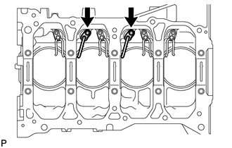
Using a 5 mm hexagon wrench, install the 2 No. 1 oil nozzles sub-assemblies with the 2 bolts.
- Torque:
- 10 N*m { 102 kgf*cm, 7 ft.*lbf }
-
-
INSTALL PISTON
-
Using a small screwdriver, install a new piston pin hole snap ring (rear side) at one end of the piston pin hole.
-
Gradually heat the piston up to 80 to 90°C (176 to 194°F).
-
Coat the piston, piston pin and connecting rod sub-assembly with engine oil.
-
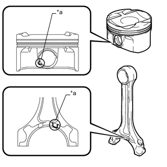
Text in Illustration *a Front Mark Align the front marks of the piston and connecting rod sub-assembly, insert the connecting rod sub-assembly into the piston, and then push in the piston pin with your thumb until the piston pin comes into contact with the piston pin hole snap ring.
Tech Tips
The piston and piston pin are a matched set.
-
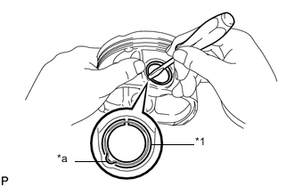
Text in Illustration *1 Piston Pin Hole Snap Ring *a Front Mark Cutout Portion Using a small screwdriver, install a new piston pin hole snap ring (front side) on the other side of the piston pin hole.
Tech Tips
Be sure that the end gap of the piston pin hole snap ring is not aligned with the front mark cutout portion of the piston.
-
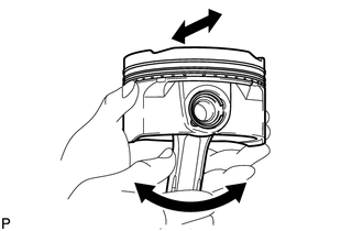
Check the fitting condition between the piston and piston pin.
-
Move the connecting rod sub-assembly back and forth on the piston pin. Check the fitting condition.
If abnormal movement is felt, replace the piston and piston pin as a set.
-
Rotate the piston back and forth on the piston pin. Check the fitting condition.
If abnormal movement is felt, replace the piston and pin as a set.
Tech Tips
Perform "Inspection After Repair" after replacing the piston Click here.
-
-
-
INSTALL PISTON RING SET
Note
During installation, use a type A piston ring set for the type A piston, and a type B piston ring set for the type B piston.
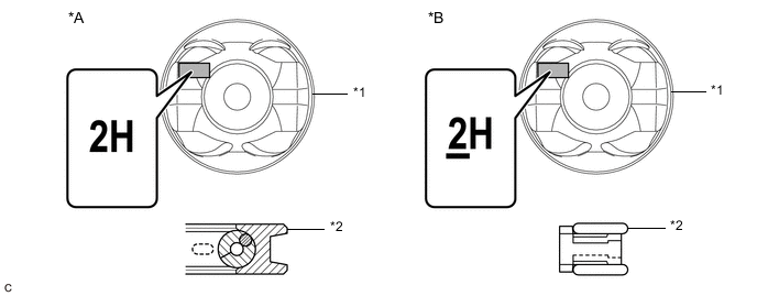
Text in Illustration *A Type A *B Type B *1 Piston *2 Oil Ring
-
Type A:
-
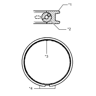
Text in Illustration *1 Oil Ring *2 Oil Ring Expander *3 Coil Joint *4 Oil Ring End Install the oil ring expander and oil ring by hand.
Tech Tips
Arrange the oil ring ends and coil joint as shown in the illustration.
-
-
Type B:
-
Text in Illustration *1 Upper Oil Ring Side Rail *2 Oil Ring Expander *3 Lower Oil Ring Side Rail Install the oil ring expander, upper oil ring side rail and lower oil ring side rail by hand.
-
-
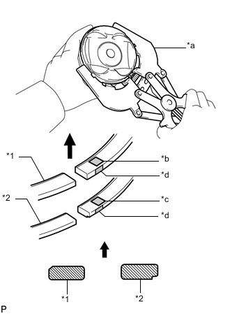
Text in Illustration *1 No. 1 Compression Ring *2 No. 2 Compression Ring *a Piston Ring Expander *b Code Mark (1N or 1NA) *c Code Mark (2N) *d Paint Mark 
Upward Using a piston ring expander, install the No. 1 compression ring and No. 2 compression ring with the code mark positioned as shown in the illustration.
Piston Ring Mark Item Code Mark No. 1 Compression Ring 1N or 1NA No. 2 Compression Ring 2N Note
Install the compression ring with the code mark facing upward.
Tech Tips
Perform "Inspection After Repair" after replacing the piston, piston ring Click here.
-
-
INSTALL CRANKSHAFT PULLEY KEY
-
Install the 2 crankshaft pulley keys to the crankshaft.
-
-
INSTALL CRANKSHAFT BEARING
-
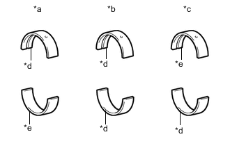
Text in Illustration *a No. 1, No. 5 Journal Bearing *b No. 2, No. 4 Journal Bearing *c No. 3 Journal Bearing *d Silver *e Black Clean the main journal and both surfaces of the crankshaft bearing and No. 2 crankshaft bearing.
-
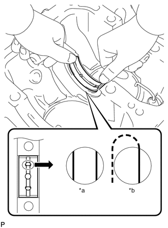
Text in Illustration *a CORRECT *b INCORRECT Install the crankshaft bearing to the cylinder block sub-assembly as shown in the illustration.
Note
-
The color of the No. 3 journal bearing is different from that of the No. 1, No. 2, No. 4 and No. 5 journal bearings. Be sure to check the color before installation.
-
Do not apply engine oil to the bearings or their contact surfaces.
-
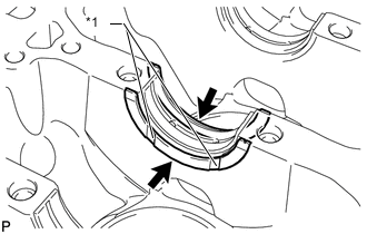
Both sides of the oil groove in the cylinder block sub-assembly should be visible through the oil feed holes in the bearing. The amount visible on each side of the holes should be equal.
-
Do not allow coolant to come into contact with the bearing inner surface.
-
If any coolant comes into contact with the bearing inner surface, replace the bearing with a new one.
-
-
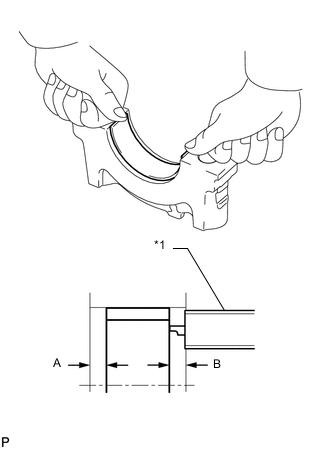
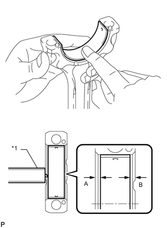
Text in Illustration *1 Vernier Caliper Install the No. 2 crankshaft bearing onto the crankshaft bearing cap.
-
Using a vernier caliper, measure the distance between the crankshaft bearing cap edge and the No. 2 crankshaft bearing edge.
Standard dimension A - B or B - A 0 to 0.7 mm (0 to 0.0276 in.) Note
-
The color of the No. 1 and No. 5 journal bearing is different from that of the No. 2, No. 3 and No. 4 journal bearings. Be sure to check the color before installation.
-
Do not apply engine oil to the bearings and the contact surfaces.
-
Do not allow coolant to come into contact with the bearing inner surface.
-
If any coolant comes into contact with the bearing inner surface, replace the bearing with a new one.
-
-
-
INSTALL CRANKSHAFT THRUST WASHER
-
Apply engine oil to the crankshaft thrust washers.
-
Text in Illustration *1 Oil Groove Install the 2 crankshaft thrust washers onto the No. 3 journal position of the cylinder block sub-assembly with the oil grooves facing outward.
-
-
INSTALL CRANKSHAFT
-
Apply engine oil to the crankshaft bearing, and install the crankshaft onto the cylinder block sub-assembly.
-
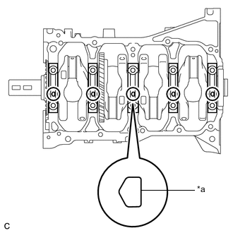
Text in Illustration *a Front Mark Examine the front marks and numbers, and install the crankshaft bearing caps onto the cylinder block sub-assembly with the front marks as shown in the illustration.
Tech Tips
The crankshaft bearing cap bolts are tightened in 3 progressive steps.
-
Apply a light coat of engine oil to the threads and under the heads of the crankshaft bearing cap bolts.
-
Step 1:
-
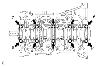
Using several steps, uniformly install and tighten the 10 crankshaft bearing cap bolts in the sequence shown in the illustration.
- Torque:
- 20 N*m { 204 kgf*cm, 15 ft.*lbf }
-
-
Step 2:
-
Tighten the 10 crankshaft bearing cap bolts again in the sequence shown in the illustration.
- Torque:
- 40 N*m { 408 kgf*cm, 30 ft.*lbf }
-
-
Step 3:
-
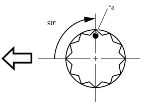
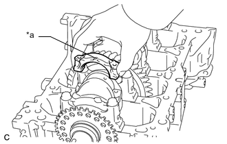
Text in Illustration *a Paint Mark 
Engine Front Mark the front of the crankshaft bearing cap bolts with paint.
-
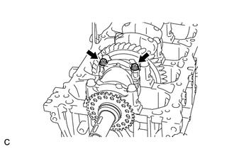
Tighten the 10 crankshaft bearing cap bolts 90° in the same sequence.
-
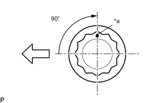
Check that the paint marks are now at a 90° angle to the front.
-
-
Check that the crankshaft turns smoothly.
-
-
INSTALL CONNECTING ROD BEARING
-
Text in Illustration *1 Vernier Caliper Clean the connecting rod bearing contact surface of the connecting rod sub-assembly and connecting rod cap, and both surfaces of both connecting rod bearings.
-
Install the connecting rod bearings to the connecting rod sub-assemblies and connecting rod caps.
-
Using a vernier caliper, measure the distance between the edges of the connecting rod sub-assembly and connecting rod bearing, and the edges of the connecting rod bearing cap and connecting rod bearing.
Standard dimension A - B or B - A 0 to 0.7 mm (0 to 0.0276 in.) Note
-
Do not apply engine oil to the connecting rod bearings and the contact surfaces.
-
Do not allow coolant to come into contact with the connecting rod bearing inner surface.
-
If any coolant comes into contact with the connecting rod bearing inner surface, replace the connecting rod bearing with a new one.
-
-
-
INSTALL PISTON WITH CONNECTING ROD
Tech Tips
Type A and type B can be distinguished by the mark on the piston and the shape of the oil ring.
Text in Illustration *A Type A *B Type B *1 Piston *2 Oil Ring
-
Apply engine oil to the cylinder walls, pistons, and surfaces of the connecting rod bearings.
-
Position the piston rings so that the ring ends are as shown in the illustration.
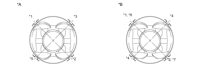
Text in Illustration *A Type A *B Type B *1 No. 1 Compression Ring *2 No. 2 Compression Ring *3 Oil Ring *4 Oil Ring Expander *5 Oil Ring Expander (Coil Joint) *6 Upper Oil Ring Side Rail *7 Lower Oil Ring Side Rail - - Tech Tips
The type B oil ring expander can be installed with the ring ends in either of the directions shown in the illustration.
-
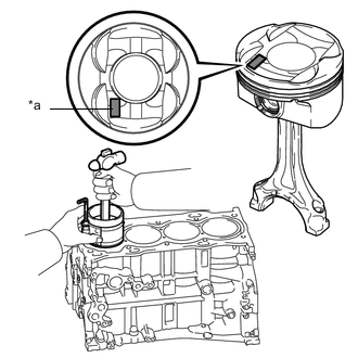
Text in Illustration *a Front Mark Using a hammer handle and piston ring compressor, press a piston with connecting rod sub-assembly into each cylinder with the front mark of the piston facing forward.
Note
When inserting the piston with connecting rod sub-assembly into the cylinder block sub-assembly, make sure the oil nozzle does not interfere with the connecting rod sub-assembly.
Tech Tips
The front mark is "2H" printed in raised letters.
-
Text in Illustration *a Front Mark Check that the front mark of the connecting rod cap is facing in the correct direction.
Note
Match the numbered connecting rod cap with the connecting rod sub-assembly.
-
Apply a light coat of engine oil to the threads and under the heads of the 2 connecting rod bolts.
-
Temporarily install the connecting rod bolts.
Tech Tips
The connecting rod bolts are tightened in 2 progressive steps.
-
Step 1:
-
Alternately tighten the 2 connecting rod bolts in several steps.
- Torque:
- 40 N*m { 408 kgf*cm, 30 ft.*lbf }
-
-
Text in Illustration *a Paint Mark Engine Front Step 2:
-
Mark the front of the 2 connecting rod bolts with paint.
-
Tighten the bolts 90° as shown in the illustration.
-
Check that the paint marks are now at a 90° angle to the front.
-
-
Check that the crankshaft turns smoothly.
-