HV RELAY ASSEMBLY INSTALLATION
PROCEDURE
-
INSTALL HYBRID BATTERY JUNCTION BLOCK ASSEMBLY
CAUTION:
Wear insulated gloves.
-
Install the hybrid battery junction block assembly to the HV battery with the 3 bolts.
- Torque:
- 7.5 N*m { 76 kgf*cm, 66 in.*lbf }
-
Connect the connector to the hybrid battery junction block assembly.
Note
The connector should be connected securely.
-
Using an insulated tool, install the 2 bolts to the hybrid battery junction block assembly.
- Torque:
- 5.4 N*m { 55 kgf*cm, 48 in.*lbf }
Note
Be sure to use a torque wrench to tighten the bolts.
-
Engage the claw and connect the terminal cover.
Note
The terminal cover should be connected securely.
-
-
INSTALL NO. 1 HYBRID BATTERY SHIELD SUB-ASSEMBLY
CAUTION:
Wear insulated gloves.
-
Install the No. 1 hybrid battery shield sub-assembly to the HV battery with the bolt and 3 nuts.
- Torque:
- 7.5 N*m { 76 kgf*cm, 66 in.*lbf }
-
Connect the connector and wire harness clamp.
Note
The connector should be connected securely.
-
-
CONNECT FRAME WIRE
CAUTION:
Wear insulated gloves.
-
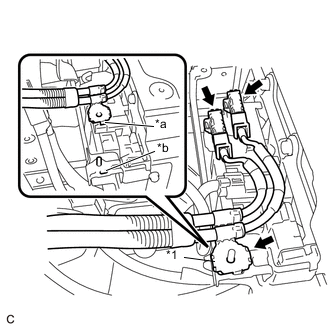
Text in Illustration *1 Shield Wire Ground *a Claw *b Hole Connect the 2 connectors to the hybrid battery junction block assembly.
Note
-
Make sure that the ends of the frame wire do not cross over each other.
-
The connectors should be connected securely.
-
-
Connect the shield wire ground to the No. 1 hybrid battery shield sub-assembly.
Note
-
Be sure to align the claw of the shield wire ground with the hole.
-
Be sure to install the shield wire ground in the correct direction.
-
-
-
INSTALL NO. 4 HYBRID BATTERY SHIELD PANEL
CAUTION:
Wear insulated gloves.
-
Install the No. 4 hybrid battery shield panel with the bolt and 2 nuts.
- Torque:
- 7.5 N*m { 76 kgf*cm, 66 in.*lbf }
-
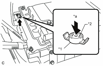
Text in Illustration *1 Battery Cover Lock Striker *2 Button *a Push Install the battery cover lock striker, then push the button to lock it.
-
-
INSTALL ROOM PARTITION PANEL INSULATOR
-
INSTALL REAR SEAT ASSEMBLY
-
INSTALL SERVICE PLUG GRIP