HV BATTERY INSTALLATION

PROCEDURE
-
INSTALL NO. 3 HV BATTERY CARRIER BRACKET SUB-ASSEMBLY (for 1-piece Type)
-
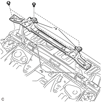
Text in Illustration *a Claw *b Hole Install the No. 3 HV battery carrier bracket sub-assembly with the 4 bolts.
- Torque:
- 19 N*m { 194 kgf*cm, 14 ft.*lbf }
Note
Be sure to align the claws of the No. 3 HV battery carrier bracket sub-assembly with the holes.
Tech Tips
Perform this procedure only when replacement of the No. 3 HV battery carrier bracket sub-assembly is necessary.
-
-
INSTALL NO. 2 HV BATTERY CARRIER BRACKET SUB-ASSEMBLY (for 2-piece Type)
-
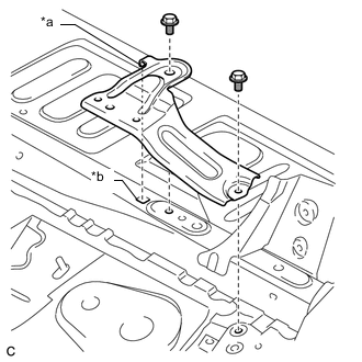
Text in Illustration *a Claw *b Hole Install the No. 2 HV battery carrier bracket sub-assembly with the 2 bolts.
- Torque:
- 19 N*m { 194 kgf*cm, 14 ft.*lbf }
Note
Be sure to align the claw of the No. 2 HV battery carrier bracket sub-assembly with the hole.
Tech Tips
Perform this procedure only when replacement of the No. 2 HV battery carrier bracket sub-assembly is necessary.
-
-
INSTALL NO. 1 HV BATTERY CARRIER BRACKET SUB-ASSEMBLY (for 2-piece Type)
-
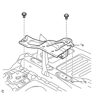
Text in Illustration *a Claw *b Hole Install the No. 1 HV battery carrier bracket sub-assembly with the 2 bolts.
- Torque:
- 19 N*m { 194 kgf*cm, 14 ft.*lbf }
Note
Be sure to align the claw of the No. 1 HV battery carrier bracket sub-assembly with the hole.
Tech Tips
Perform this procedure only when replacement of the No. 1 HV battery carrier bracket sub-assembly is necessary.
-
-
INSTALL NO. 2 HV BATTERY PACK WIRE
CAUTION:
Wear insulated gloves.
-
Connect the HV battery connector and 5 clamps, and install the No. 2 HV battery pack wire to the HV battery.
-
-
INSTALL HV BATTERY JUNCTION BLOCK ASSEMBLY
-
INSTALL NO. 1 HYBRID BATTERY SHIELD SUB-ASSEMBLY
CAUTION:
Wear insulated gloves.
-
Install the No. 1 hybrid battery shield sub-assembly to the HV battery with the bolt and 3 nuts.
- Torque:
- 7.5 N*m { 76 kgf*cm, 66 in.*lbf }
-
-
INSTALL BATTERY SMART UNIT
CAUTION:
Wear insulated gloves.
-
w/ No. 1 HV Battery LH Cover Bracket:
-
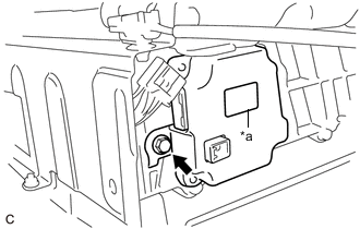
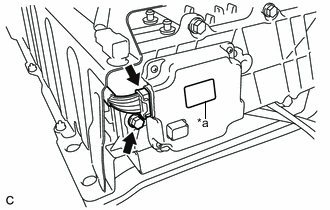
Text in Illustration *a Purple Label Install the battery smart unit to the HV battery with the bolt.
- Torque:
- 7.5 N*m { 76 kgf*cm, 66 in.*lbf }
Note
Check color of the label.
-
Install the wiring harness protector to the battery smart unit connector.
-
Connect the battery smart unit connector.
Note
The connector should be connected securely.
-
Engage the 2 claws to install the wiring harness protector cover to the battery smart unit connector.
-
-
w/o No. 1 HV Battery LH Cover Bracket:
-
Text in Illustration *a Black Label Install the battery smart unit to the HV battery with the bolt.
- Torque:
- 7.5 N*m { 76 kgf*cm, 66 in.*lbf }
Note
Check color of the label.
-
Connect the battery smart unit connector.
Note
The connector should be connected securely.
-
-
-
INSTALL NO. 2 HV BATTERY SHIELD PANEL
CAUTION:
Wear insulated gloves.
-
w/ No. 1 HV Battery LH Cover Bracket:
-
Install the No. 2 HV battery shield panel to the HV battery with the 2 bolts.
- Torque:
- 7.5 N*m { 76 kgf*cm, 66 in.*lbf }
-
Engage the 3 wire harness clamps to the No. 2 HV battery shield panel.
-
Connect the battery smart unit connector.
-
-
w/o No. 1 HV Battery LH Cover Bracket:
-
Install the No. 2 HV battery shield panel to the HV battery with the 2 bolts and nut.
- Torque:
- 7.5 N*m { 76 kgf*cm, 66 in.*lbf }
-
Connect the 3 wire harness clamps to the No. 2 HV battery shield panel.
-
Connect the battery smart unit connector.
-
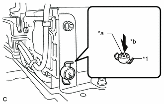
Text in Illustration *1 Battery Cover Lock Striker *a Button *b Push Install the battery cover lock striker, then push the button to lock it.
-
-
-
REMOVE NO. 1 HV BATTERY LH COVER BRACKET (w/ Bracket)
-
INSTALL HV BATTERY
CAUTION:
Wear insulated gloves.
-
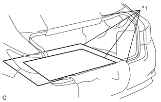
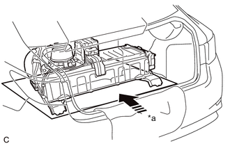
Text in Illustration *1 Cardboard Place a piece of cardboard in the luggage compartment.
-
Using a suitable adaptor such as a rope, install the HV battery to the vehicle in the same direction it was facing during removal.
Note
Use cardboard or other similar material to protect the HV battery and vehicle body from damage.
-
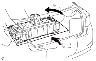
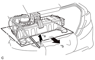
Text in Illustration *a Push *b Turn 180° Push the cardboard and HV battery together to the middle of the luggage compartment.
-
Turn the cardboard and HV battery 180° together.
-
Install the 2 clips.
-
Install the battery cooling blower assembly to the HV battery with the 3 nuts.
- Torque:
- 7.5 N*m { 76 kgf*cm, 66 in.*lbf }
Note
-
Be sure not to touch the fan part of the battery cooling blower assembly.
-
Do not lift the battery cooling blower assembly using the wire harness.
-
Connect the connector to the battery cooling blower assembly.
-
Engage the 2 claws to install the No. 2 hybrid battery intake duct.
Note
Ensure that the duct is installed securely.
-
Install the clip.
-
Install the upper No. 2 HV battery cover bracket with the 2 nuts.
- Torque:
- 7.5 N*m { 76 kgf*cm, 66 in.*lbf }
-
Text in Illustration *a Push Push the HV battery together with the cardboard toward the front of the vehicle.
Note
Align the holes for the HV battery holding bolts.
-
Text in Illustration *a Hold up *b Pull out Use a tire lever to hold up the HV battery and pull out the cardboard.
-
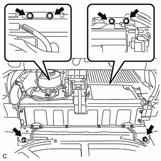
Text in Illustration *a Ground Bolt Install the HV battery with the 6 bolts.
- Torque:
- 19 N*m { 194 kgf*cm, 14 ft.*lbf }
Tech Tips
Install the ground bolt to the locations shown in the illustration.
-
Connect the battery smart unit connector and No. 2 HV battery pack wire connector.
-
Connect the HV battery junction block assembly connector and wire harness clamp.
-
-
CONNECT FRAME WIRE
-
INSTALL NO. 4 HV BATTERY SHIELD PANEL
-
INSTALL NO. 1 HYBRID BATTERY INTAKE DUCT
-
INSTALL ROOM PARTITION PANEL INSULATOR
-
INSTALL REAR SEAT SIDE GARNISH LH
-
INSTALL REAR DOOR SCUFF PLATE LH
-
INSTALL REAR SEAT ASSEMBLY
-
INSTALL LUGGAGE COMPARTMENT INNER TRIM COVER LH
-
INSTALL ROPE HOOK (for LH Side)
-
INSTALL LUGGAGE HOLD BELT STRIKER ASSEMBLY (for LH Side)
-
INSTALL LUGGAGE COMPARTMENT INNER TRIM COVER RH (w/o Power Trunk Lid System)
-
INSTALL LUGGAGE COMPARTMENT INNER TRIM COVER RH (w/ Power Trunk Lid System)
-
INSTALL ROPE HOOK (for RH Side)
-
INSTALL REAR FLOOR FINISH PLATE
-
INSTALL LUGGAGE HOLD BELT STRIKER ASSEMBLY (for Rear Side)
-
INSTALL SPARE WHEEL COVER PAD RH
-
INSTALL SPARE WHEEL COVER PAD LH
-
INSTALL AUXILIARY BATTERY
-
INSTALL SERVICE PLUG GRIP