WIPER AND WASHER SYSTEM TERMINALS OF ECU
-
CHECK WINDSHIELD WIPER RELAY ASSEMBLY (w/ Auto Wiper System)

-
Disconnect the F56 windshield wiper relay assembly connector.
-
Measure the voltage and resistance on the wire harness side connector according to the value(s) in the table below.
Terminal No.
(Symbol)
Wiring Color Terminal Description Condition Specified Condition F56-2 (IG) - Body ground B - Body ground Ignition switch ON signal (Power source circuit) Ignition switch ON 11 to 14 V Ignition switch off Below 1 V F56-25 (W) - Body ground B - Body ground Front washer switch signal Front washer switch on Below 1 Ω Front washer switch off 10 kΩ or higher F56-8 (VR2) - F56-21 (VR1) W - G Adjusting volume signal Controlling sensitivity setting switch* changed 0 to 231 Ω F56-12 (E) - Body ground W-B - Body ground Body ground Always Below 1 Ω F56-16 (WIG) - Body ground B - Body ground Power source signal Ignition switch ON 11 to 14 V Ignition switch off Below 1 V Tech Tips
*: The rain sensor sensitivity can be adjusted by the controlling sensitivity setting switch.
If the result is not as specified, there may be a malfunction in the wire harness.
-
-
Reconnect the F56 windshield wiper relay assembly connector.
-
Measure the resistance according to the value(s) in the table below.
Terminal No.
(Symbol)
Wiring Color Terminal Description Condition Specified Condition F56-10 (+1) - Body ground G - Body ground Front wiper motor low speed signal Front wiper motor off Below 1 Ω Tech Tips
If the result is not as specified, the windshield wiper relay assembly may be malfunctioning.
-
Measure the voltage and check for pulses according to the value(s) in the table below.
Terminal No.
(Symbol)
Wiring Color Terminal Description Condition Specified Condition F56-1 (+SM) - Body ground G - Body ground Front wiper motor position detection signal Front wiper motor in low or high operation Below 1 V ←→ 11 to 14 V Front wiper motor off Below 1 V F56-3 (C1) - F56-5 (CO) V - Y Front wiper switch AUTO signal Ignition switch ON, front wiper switch in AUTO Below 1 V Ignition switch ON, front wiper switch off 11 to 14 V F56-25 (W) - Body ground B - Body ground Front washer switch signal Ignition switch ON, front washer switch on Below 1 V Ignition switch ON, front washer switch off 11 to 14 V F56-10 (+1) - Body ground G - Body ground Front wiper motor low speed signal Front wiper motor in low operation 11 to 14 V F56-11 (+2) - Body ground W - Body ground Front wiper motor high speed signal Front wiper motor in high operation 11 to 14 V Front wiper motor off Below 1 V F56-14 (MPX1) - Body ground V - Body ground Rain sensor signal Ignition switch ON Pulse generation F56-24 (SPD) - Body ground V - Body ground Vehicle speed signal Driving at approximately 20 km/h (12 mph) Pulse generation (See waveform 1) Tech Tips
If the result is not as specified, the windshield wiper relay assembly may be malfunctioning.
-
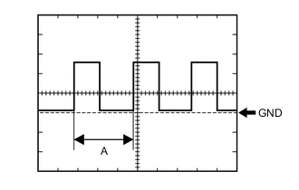
Waveform 1 (Reference):
Item Condition Tester Connection F56-24 (SPD) - Body ground Tool Setting 5 V/DIV., 20 ms./DIV. Vehicle Condition Driving at approximately 20 km/h (12 mph) Tech Tips
When the system is functioning normally, one wheel revolution generates 4 pulses. As the vehicle speed increases, the width indicated by A in the illustration narrows.
-
-
-
CHECK COMBINATION METER ASSEMBLY
-
Measure the voltage according to the value(s) in the table below.
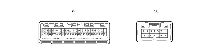
Terminal No. (Symbol) Wiring Color Terminal Description Condition Specified Condition F4-17 (WLVL)* - Body ground LG - Body ground Washer fluid level signal Ignition switch ON, washer fluid level not low 11 to 14 V Ignition switch ON, washer fluid level low Below 1 V
-
*: w/ Washer Fluid Warning System
-
-
Measure the waveform according to the value(s) in the table below.
Terminal No. (Symbol) Wiring Color Terminal Description Condition Specified Condition F4-6 (+S) - Body ground V - Body ground Speed signal for other system (Output) Driving at approximately 20 km/h (12 mph) Pulse generation (See waveform 1)
-
Waveform 1 (Reference):
Item Condition Tester Connection F4-6 (+S) - Body ground Tool Setting 5 V/DIV., 20 ms./DIV. Vehicle Condition Driving at approximately 20 km/h (12 mph) Tech Tips
When the system is functioning normally, one wheel revolution generates 4 pulses. As the vehicle speed increases, the width indicated by A in the illustration narrows.
-
-
-
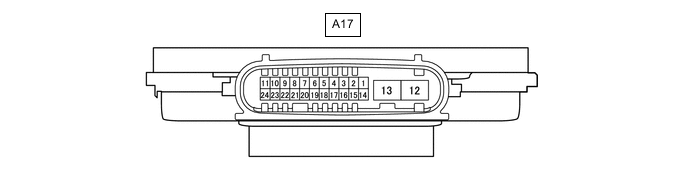
HEADLIGHT ECU SUB-ASSEMBLY RH (for LED Headlight with Headlight Cleaner System)
-
Disconnect the A17 headlight ECU sub-assembly RH connector.
-
Measure the resistance and voltage according to the value(s) in the table below.
Tech Tips
Measure the values on the wire harness side with the connector disconnected.
Terminal No. (Symbol) Wiring Color Terminal Description Condition Specified Condition A17-4 (IG) - Body ground V - Body ground IG power supply Ignition switch off Below 1 V Ignition switch ON 11 to 14 V A17-12 (GND) - Body ground W-B - Body ground Body ground Always Below 1 Ω -
Reconnect the A17 headlight ECU sub-assembly RH connector.
-
Measure the voltage according to the value(s) in the table below.
Terminal No. (Symbol) Wiring Color Terminal Description Condition Specified Condition A17-7 (HLC) - Body ground W - Body ground Headlight cleaner motor operation signal Headlight cleaner motor not operating 11 to 14 V Headlight cleaner motor operating Below 1 V A17-18 (FRWA) - Body ground R - Body ground Front washer switch signal Ignition switch ON, front washer switch on 11 to 14 V Ignition switch ON, front washer switch off Below 1 V
-
-
CHECK INSTRUMENT PANEL JUNCTION BLOCK ASSEMBLY AND MAIN BODY ECU (MULTIPLEX NETWORK BODY ECU) (for Halogen Headlight with Headlight Cleaner System)
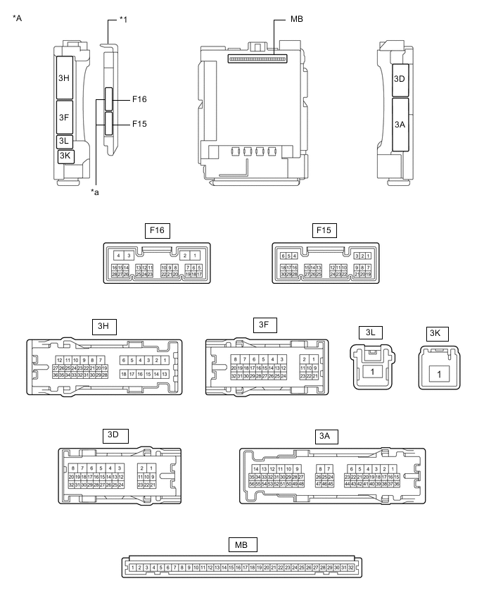
*A Main Body ECU (Multiplex Network Body ECU) with 2 Connectors - - *1 Main Body ECU (Multiplex Network Body ECU) - - *a 2 Connectors - - 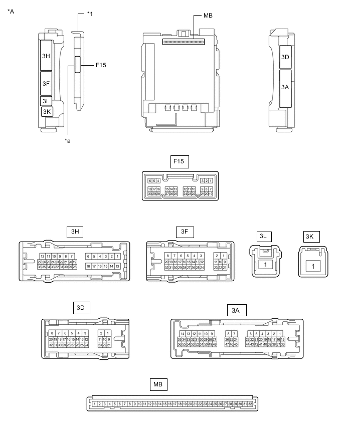
*A Main Body ECU (Multiplex Network Body ECU) with 1 Connector - - *1 Main Body ECU (Multiplex Network Body ECU) - - *a 1 Connector - -
-
Measure the voltage according to the value(s) in the table below.
Terminal No. (Symbol) Wiring Color Terminal Description Condition Specified Condition 3F-31 - Body ground G- Body ground Low beam headlight signal Light control switch in head position Below 1 V Light control switch off 4.2 V or higher If the result is not as specified, the main body ECU (multiplex network body ECU) or instrument panel junction block assembly may be malfunctioning.
-