FRONT DOOR ADJUSTMENT

CAUTION / NOTICE / HINT
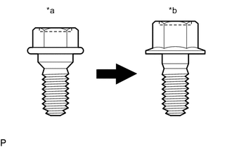
| *a | Centering Bolt |
| *b | Standard Bolt |
Tech Tips
-
Use the same procedure for the RH side and LH side.
-
The following procedure is for the LH side.
-
Centering bolts are used to install the door hinges to the vehicle body and door. The door cannot be adjusted with the centering bolts installed. Substitute the centering bolts with standard bolts when making adjustments.
-
The specified torque for standard bolts is shown in the standard bolt chart.
PROCEDURE
-
INSPECT FRONT DOOR PANEL SUB-ASSEMBLY
-
Check that the clearance measurements of areas "A" to "Y" are within the standard ranges.

Standard Clearance Area Measurement Area Measurement A 2.1 to 6.1 mm (0.083 to 0.240 in.) B -2.0 to 2.0 mm (-0.079 to 0.079 in.) C 3.1 to 7.1 mm (0.122 to 0.280 in.) D 2.9 to 6.9 mm (0.114 to 0.272 in.) E 3.3 to 6.7 mm (0.130 to 0.264 in.) F 7.1 to 11.1 mm (0.280 to 0.437 in.) G 3.3 to 6.7 mm (0.130 to 0.264 in.) H 5.9 to 9.9 mm (0.232 to 0.390 in.) I 3.3 to 6.7 mm (0.130 to 0.264 in.) J 3.7 to 7.7 mm (0.146 to 0.303 in.) K 3.3 to 6.7 mm (0.130 to 0.264 in.) L 1.4 to 5.4 mm (0.055 to 0.213 in.) M 3.3 to 6.7 mm (0.130 to 0.264 in.) N 1.2 to 5.2 mm (0.047 to 0.205 in.) O 3.3 to 6.7 mm (0.130 to 0.264 in.) P 0.8 to 3.8 mm (0.031 to 0.150 in.) Q 2.4 to 6.4 mm (0.094 to 0.252 in.) R -2.0 to 2.0 mm (-0.079 to 0.079 in.) S 2.9 to 5.3 mm (0.114 to 0.209 in.) T -1.2 to 1.2 mm (-0.047 to 0.047 in.) U 7.5 to 11.5 mm (0.295 to 0.453 in.) V -2.0 to 2.0 mm (-0.079 to 0.079 in.) W 3.5 to 8.5 mm (0.138 to 0.335 in.) X 2.7 to 5.7 mm (0.106 to 0.224 in.) Y -1.5 to 1.5 mm (-0.059 to 0.059 in.) - -
-
-
ADJUST FRONT DOOR PANEL SUB-ASSEMBLY
-
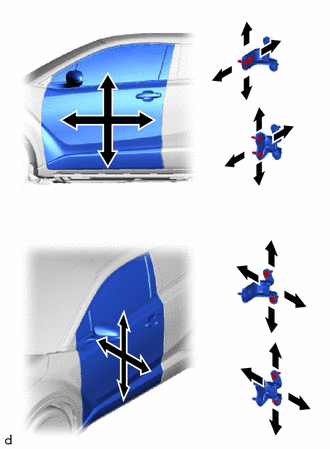
Using SST, loosen the 4 hinge bolts on the vehicle body and adjust the door position.
- SST
- 09812-00010
-
Tighten the 4 hinge bolts on the vehicle body after adjustment.
- Torque:
- 26 N*m { 265 kgf*cm, 19 ft.*lbf }
-
Loosen the 4 hinge bolts on the door and adjust the door position.
-
Tighten the 4 hinge bolts on the door after adjustment.
- Torque:
- for TMMT Made
- 26 N*m { 265 kgf*cm, 19 ft.*lbf }
- for TMC Made
- 21 N*m { 214 kgf*cm, 15 ft.*lbf }
-
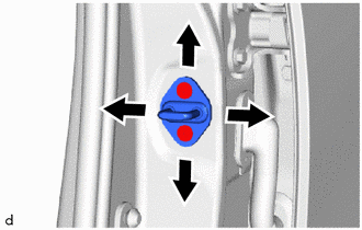
Using a T40 "TORX" socket wrench, slightly loosen the 2 striker mounting screws.
-
Using a brass bar and a hammer, hit the striker to adjust its position.
-
Using a T40 "TORX" socket wrench, tighten the 2 striker mounting screws after adjustment.
- Torque:
- 23 N*m { 235 kgf*cm, 17 ft.*lbf }
-