POWER MIRROR CONTROL SYSTEM AUTO Power Retract Mirrors do not operate
DESCRIPTION
The outer mirror switch assembly sends a mirror auto retract/return signal to the main body ECU (multiplex network body ECU) when the retractable outer mirror switch on the outer mirror switch assembly is in the AUTO position. The main body ECU (multiplex network body ECU) retracts or returns the outer rear view mirror assemblies based on the lock/unlock signal of each door while the ignition switch is off.
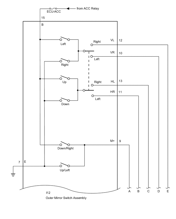
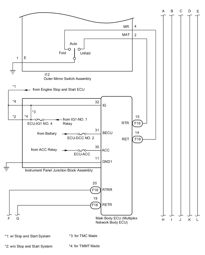
WIRING DIAGRAM
-
for LHD
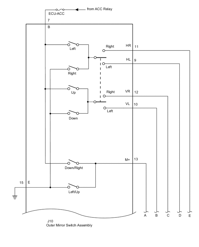
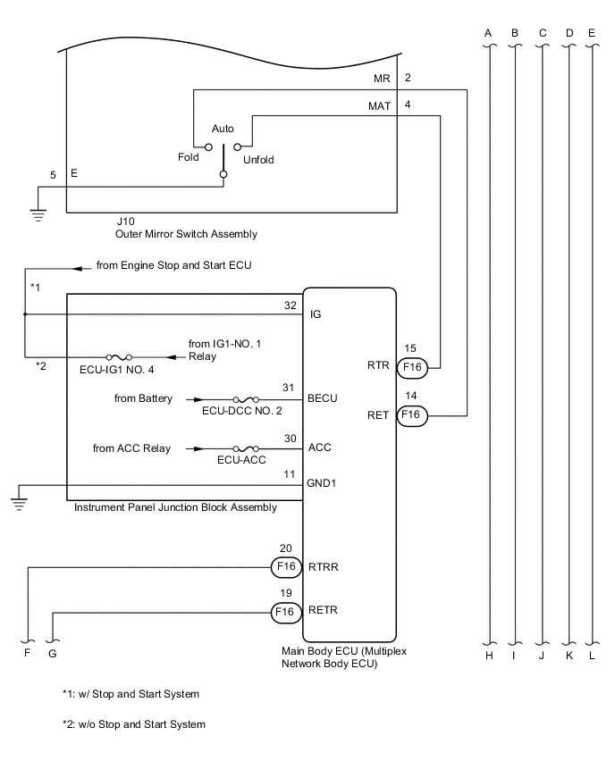
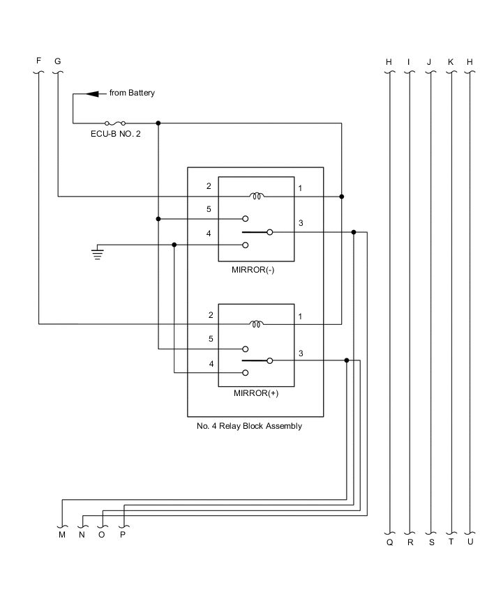
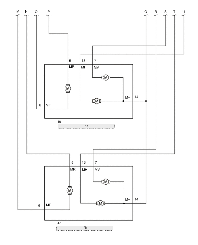
*a Outer Rear View Mirror Assembly RH *b Outer Rear View Mirror Assembly LH -
for RHD

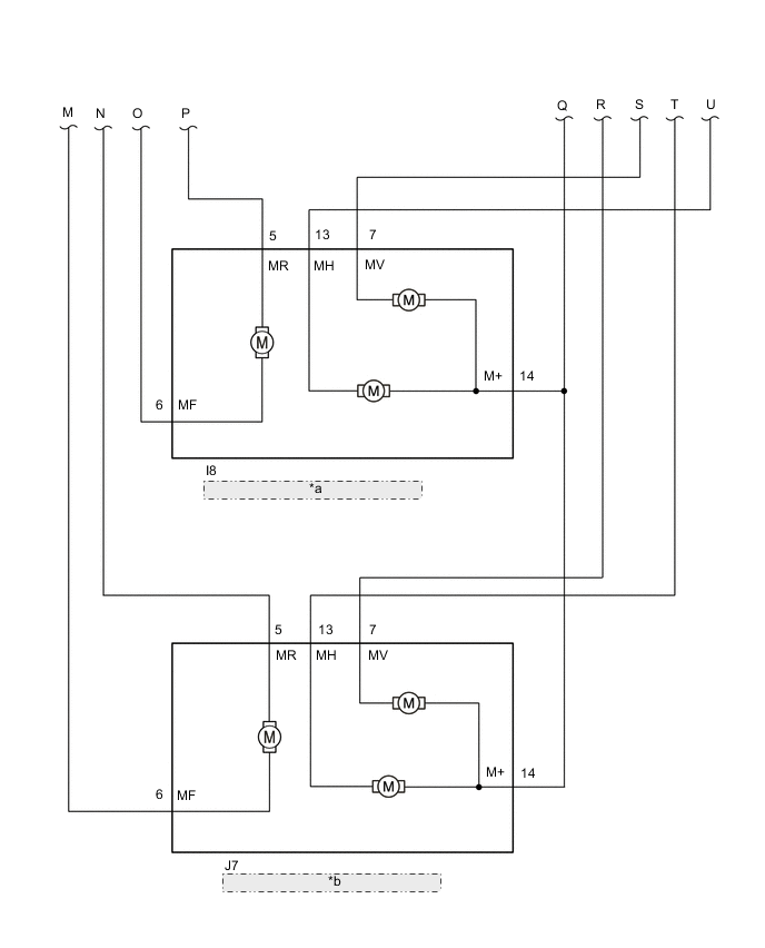
for TMMT Made *a Outer Rear View Mirror Assembly RH *b Outer Rear View Mirror Assembly LH 
for TMC Made *a Outer Rear View Mirror Assembly RH *b Outer Rear View Mirror Assembly LH
CAUTION / NOTICE / HINT
Note
-
Inspect the fuses for circuits related to this system before performing the following procedure.
-
If the main body ECU (multiplex network body ECU) is replaced, refer to Service Bulletin.*1
-
*1: w/ Entry and Start System
PROCEDURE
-
CHECK POWER RETRACT MIRROR FUNCTION
-
Check the power retract mirror function.
OK Power retract mirror function operates normally. Result Proceed to OK NG
NG 
GO TO OTHER DIAGNOSIS PROCEDURE (Power Retractable Mirrors do not Operate with Power Retract Mirror Switch) Click here
OK 
-
-
CHECK POWER DOOR LOCK CONTROL SYSTEM
-
Check the power door lock control system.
OK Power door lock control system is normal. Result Proceed to OK NG
NG
GO TO POWER DOOR LOCK CONTROL SYSTEM Click here
OK
-
-
CHECK WIRELESS DOOR LOCK CONTROL SYSTEM
-
w/ Entry and Start System
-
Check the wireless door lock control system.
-
-
w/o Entry and Start System
-
Check the wireless door lock control system.
OK Wireless door lock control system is normal. Result Result Proceed to OK (w/ Entry and Start System) A OK (w/o Entry and Start System) B NG (w/ Entry and Start System) C NG (w/o Entry and Start System) D -
B 
GO TO STEP 5 Click here
C
GO TO WIRELESS DOOR LOCK CONTROL SYSTEM Click here
D
GO TO WIRELESS DOOR LOCK CONTROL SYSTEM Click here
A
-
-
CHECK ENTRY AND START SYSTEM (for Entry Function)
-
Check the entry and start system (for Entry Function).
OK Entry and start system (for Entry Function) is normal. Result Proceed to OK NG
NG
GO TO ENTRY AND START SYSTEM (for Entry Function) Click here
OK
-
-
READ VALUE USING GTS
-
Connect the GTS to the DLC3.
-
Turn the ignition switch to ON.
-
Turn the GTS on.
-
Enter the following menus: Body Electrical / Main Body / Data List.
-
Read the Data List according to the display on the GTS.
Body Electrical > Main Body > Data ListTester Display Measurement Item Range Normal Condition Diagnostic Note Auto Mirror SW Retractable outer mirror switch signal OFF or ON OFF: Mirror retract switch not in auto position
ON: Mirror retract switch in auto position
-
Body Electrical > Main Body > Data ListTester Display Auto Mirror SW OK On the GTS screen, ON or OFF is displayed accordingly. Result Result Proceed to OK (for LHD) A OK (for RHD) B NG C
A
REPLACE MAIN BODY ECU (MULTIPLEX NETWORK BODY ECU) Click here
B
REPLACE MAIN BODY ECU Click here
C
-
-
INSPECT OUTER MIRROR SWITCH ASSEMBLY
-
Remove the outer mirror switch assembly.
-
Inspect the outer mirror switch assembly.
Result Proceed to OK NG
NG
REPLACE OUTER MIRROR SWITCH ASSEMBLY Click here
OK
-
-
CHECK HARNESS AND CONNECTOR (OUTER MIRROR SWITCH ASSEMBLY - MAIN BODY ECU (MULTIPLEX NETWORK BODY ECU))
-
Disconnect the I12*1 or J10*2 outer mirror switch assembly.
-
*1: for RHD
-
*2: for LHD
-
-
Disconnect the F16 main body ECU (multiplex network body ECU).
-
Measure the resistance according to the value(s) in the table below.
Standard Resistance for RHD Tester Connection Condition Specified Condition I12-2 (MAT) - F16-15 (RTR) Always Below 1 Ω I12-2 (MAT) or F16-15 (RTR) - Body ground Always 10 kΩ or higher for LHD Tester Connection Condition Specified Condition J10-4 (MAT) - F16-15 (RTR) Always Below 1 Ω J10-4 (MAT) or F16-15 (RTR) - Body ground Always 10 kΩ or higher Result Result Proceed to OK (for LHD) A OK (for RHD) B NG C
A
REPLACE MAIN BODY ECU (MULTIPLEX NETWORK BODY ECU) Click here
B
REPLACE MAIN BODY ECU (MULTIPLEX NETWORK ECU) Click here
C
REPAIR OR REPLACE HARNESS OR CONNECTOR
-