WINDSHIELD DEICER SYSTEM TERMINALS OF ECU
-
CHECK AIR CONDITIONING AMPLIFIER ASSEMBLY
-
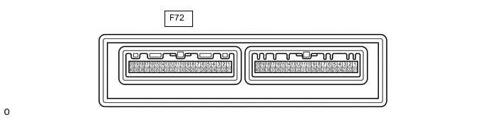
Disconnect the F72 air conditioning amplifier assembly connector.
-
Measure the voltage and resistance according to the value(s) in the table below.
Tester Connection Wiring Color Terminal Description Condition Specified Condition F72-5 (IG+) - Body ground B - Body ground Power source (IG) Ignition switch ON 11 to 14 V Ignition switch off Below 1 V F72-1 (B) - Body ground V - Body ground Battery power supply Always 11 to 14 V F72-29 (GND) - Body ground W-B - Body ground Ground Always Below 1 Ω -
Reconnect the F72 air conditioning amplifier assembly connector.
-
Measure the voltage according to the value(s) in the table below.
Tester Connection Wiring Color Terminal Description Condition Specified Condition F72-24 (FDEF) - Body ground W - Body ground Wiper deicer signal Ignition switch ON, windshield deicer switch on Below 1 V Ignition switch ON, windshield deicer switch off 11 to 14 V F72-3 (LIN1) - Body ground L - Body ground LIN communication line Ignition switch ON Pulse generation
-
-
CHECK AIR CONDITIONING CONTROL ASSEMBLY

-
Check for pulse according to the value(s) in the table below.
Terminal No. (Symbol) Wiring Color Terminal Description Condition Specified Condition F61-2 (LIN1) - F61-16 (GND) L - W-B LIN communication line Ignition switch ON Pulse generation
-