WINDOW DEFOGGER SYSTEM TERMINALS OF ECU
-
CHECK AIR CONDITIONING AMPLIFIER ASSEMBLY (for TMMT MADE)
-
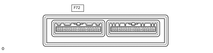
Disconnect the F72 air conditioning amplifier assembly connector.
-
Measure the voltage and resistance according to the value(s) in the table below.
Tech Tips
Measure the values on the wire harness side with the connector disconnected.
Tester Connection Wiring Color Terminal Description Condition Specified Condition F72-5 (IG+) - F72-29 (GND) B - W-B Power source (IG) Ignition switch ON 11 to 14 V F72-5 (IG+) - F72-29 (GND) B - W-B Power source (IG) Ignition switch off Below 1 V F72-1 (B) - F72-29 (GND) V - W-B Battery power supply Always 11 to 14 V F72-29 (GND) - Body ground W-B - Body ground Ground Always Below 1 Ω If the result is not as specified, there may be a malfunction in the wire harness.
-
Reconnect the F72 air conditioning amplifier assembly connector.
-
Measure the voltage and check for pulses according to the value(s) in the table below.
Tester Connection Wiring Color Terminal Description Condition Specified Condition F72-26 (RDFG) - F72-29 (GND) P - W-B Rear window defogger signal Ignition switch ON, rear window defogger switch off 11 to 14 V F72-26 (RDFG) - F72-29 (GND) P - W-B Rear window defogger signal Ignition switch ON, rear window defogger switch on Below 1 V F72-3 (LIN1) - F72-29 (GND) L - W-B*1
BE - W-B*2
LIN communication line Ignition switch ON Pulse generation If the result is not as specified, the air conditioning amplifier assembly may be malfunctioning.
-
*1: for LHD
-
*2: for RHD
-
-
-
CHECK AIR CONDITIONING AMPLIFIER ASSEMBLY (for TMC MADE)
-
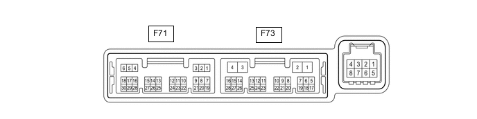
Disconnect the F73 air conditioning amplifier assembly connector.
-
Measure the voltage and resistance according to the value(s) in the table below.
Tech Tips
Measure the values on the wire harness side with the connector disconnected.
Tester Connection Wiring Color Terminal Description Condition Specified Condition F73-2 (IG+) - F73-4 (GND) B - W-B Power source (IG) Ignition switch ON 11 to 14 V F73-2 (IG+) - F73-4 (GND) B - W-B Power source (IG) Ignition switch off Below 1 V F73-1 (B) - F73-4 (GND) V - W-B Battery power supply Always 11 to 14 V F73-4 (GND) - Body ground W-B - Body ground Ground Always Below 1 Ω If the result is not as specified, there may be a malfunction in the wire harness.
-
Reconnect the F73 air conditioning amplifier assembly connector.
-
Measure the voltage and check for pulses according to the value(s) in the table below.
Tester Connection Wiring Color Terminal Description Condition Specified Condition F73-5 (RDFG) - F73-4 (GND) P - W-B Rear window defogger signal Ignition switch ON, rear window defogger switch off 11 to 14 V F73-5 (RDFG) - F73-4 (GND) P - W-B Rear window defogger signal Ignition switch ON, rear window defogger switch on Below 1 V F73-14 (LIN1) - F73-4 (GND) BE - W-B LIN communication line Ignition switch ON Pulse generation If the result is not as specified, the air conditioning amplifier assembly may be malfunctioning.
-
-
CHECK AIR CONDITIONING CONTROL ASSEMBLY
-
Check for pulses according to the value(s) in the table below.

Tester Connection Wiring Color Terminal Description Condition Specified Condition F61-2 (LIN1) - F61-16 (GND) L - W-B*1
BE - W-B*2
LIN communication line Ignition switch ON Pulse generation
-
*1: for TMMT Made
-
*2: for TMC Made
If the result is not as specified, the air conditioning control assembly may be malfunctioning.
-
-