INSTRUMENT PANEL SAFETY PAD INSTALLATION
Info Added 2017-10-06 ![]()
CAUTION / NOTICE / HINT
Tech Tips
-
Use the same procedure for LHD and RHD vehicles.
-
The procedure listed below is for the LHD vehicles.
PROCEDURE
-
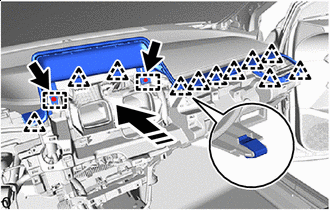
INSTALL INSTRUMENT PANEL SAFETY PAD SUB-ASSEMBLY
-
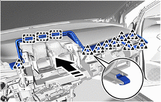
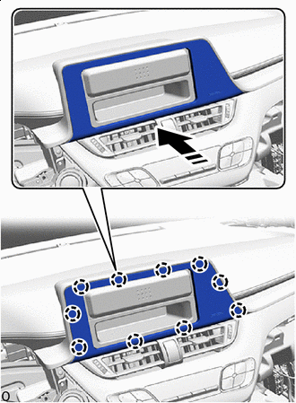
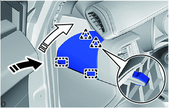
Engage the guides to install the instrument panel safety pad sub-assembly as shown in the illustration.
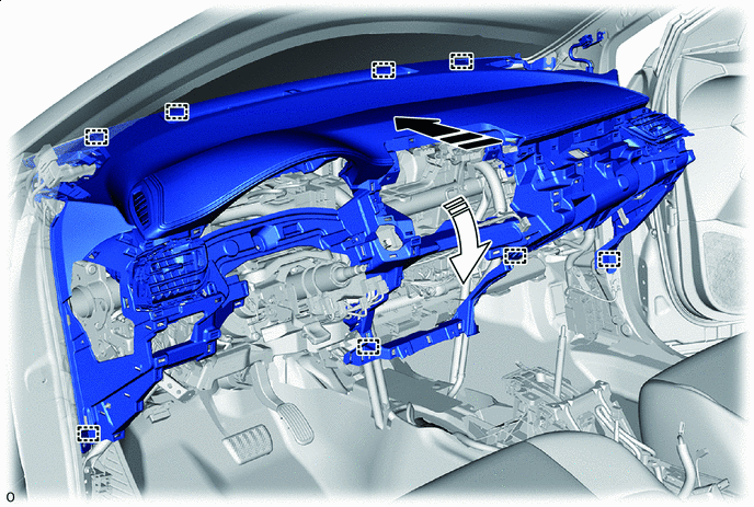

Install in this Direction (1) 
Install in this Direction (2) -
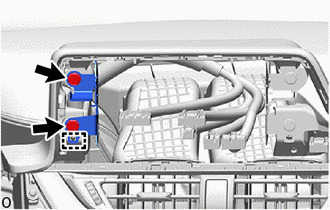
Engage each clamp.
-
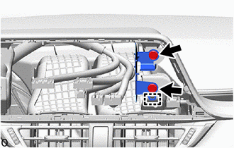
Connect each connector.
-
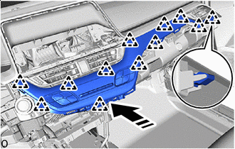
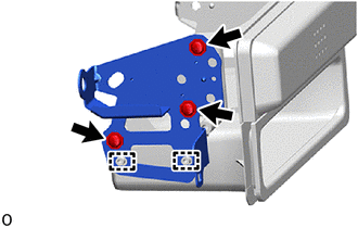
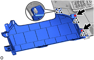
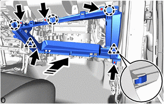
for TMMT Made:
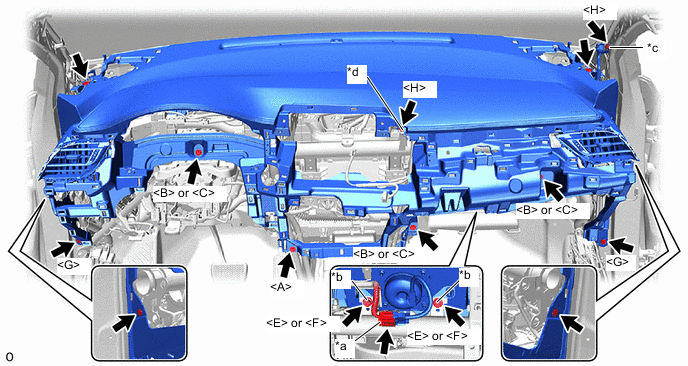
*a Airbag Connecor *b Airbag Bolt *c Ground Bolt A *d Ground Bolt B
-
Connect the airbag connector.
-
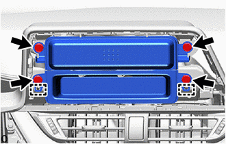
Install the 4 clips.
-
Install the 10 bolts as shown in the illustration.
- Torque:
- Airbag bolt
- 20 N*m { 204 kgf*cm, 15 ft.*lbf }
- Ground bolt A
- 10.5 N*m { 107 kgf*cm, 8 ft.*lbf }
- Ground bolt B
- 8.3 N*m { 85 kgf*cm, 73 in.*lbf }
-
-
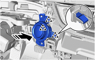
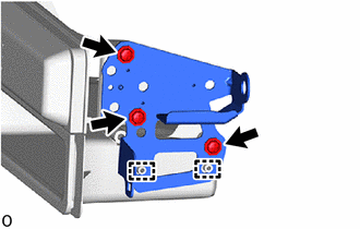
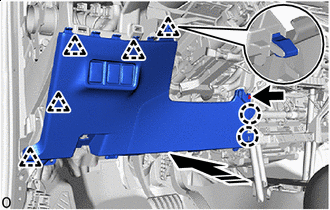
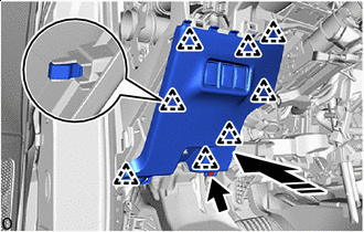
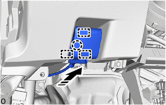
except TMMT Made:
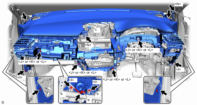
*a Airbag Connecor *b Airbag Bolt *c Ground Bolt - -
-
Connect the airbag connector.
-
Install the 4 clips.
-
Install the 10 bolts as shown in the illustration.
- Torque:
- Airbag bolt
- 20 N*m { 204 kgf*cm, 15 ft.*lbf }
- Ground bolt
- 8.3 N*m { 85 kgf*cm, 73 in.*lbf }
-
-
-
INSTALL NO. 2 HEATER TO REGISTER DUCT SUB-ASSEMBLY
-
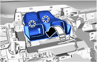
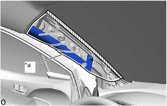
Install in this Direction Engage the claws to install the No. 2 heater to register duct sub-assembly as shown in the illustration.
-
-
INSTALL NO. 1 INSTRUMENT PANEL GARNISH SUB-ASSEMBLY (w/ Display)
-
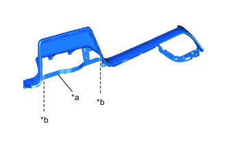
*a Runner Portion *b Cut Off When installing a new No. 1 instrument panel garnish sub-assembly:
-
Using a nipper, cut off both ends of the runner portion as shown in the illustration.
-
-
Install in this Direction Engage the clips and guides to install the No. 1 instrument panel garnish sub-assembly as shown in the illustration.
-
Install the 2 bolts <G>.
-
-
INSTALL RADIO AND DISPLAY RECEIVER ASSEMBLY WITH BRACKET (for Radio and Display Type)
-
INSTALL INSTRUMENT PANEL CENTER REGISTER ASSEMBLY
-
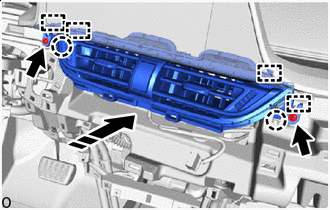
Install in this Direction Engage the guides and claws to install the instrument panel center register assembly as shown in the illustration.
-
Install the 2 screws <D> or 2 screws <M>.
-
-
INSTALL NO. 1 INSTRUMENT PANEL GARNISH SUB-ASSEMBLY (w/o Display)
-
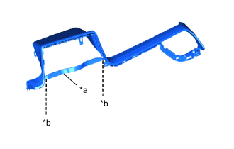
*a Runner Portion *b Cut Off When installing a new No. 1 instrument panel garnish sub-assembly:
-
Using a nipper, cut off both ends of the runner portion as shown in the illustration.
-
-
Install in this Direction Engage the guides and clips to install the No. 1 instrument panel garnish sub-assembly as shown in the illustration.
-
-
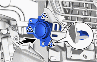
INSTALL STARTER SWITCH BEZEL (for LHD with Entry and Start System)
-
Connect the connector.
-
Install in this Direction Engage the clips to install the starter switch bezel as shown in the illustration.
-
-
INSTALL INSTRUMENT CLUSTER FINISH LOWER CENTER PANEL SUB-ASSEMBLY
-
Connect the connector.
-
Install in this Direction Engage the clips to install the instrument cluster finish lower center panel sub-assembly as shown in the illustration.
-
-
INSTALL NO. 1 RADIO BRACKET (w/o Cover)
-
Engage the guides to install the No. 1 radio bracket.
-
Install the 2 bolts <G> or 2 bolts <I>.
-
-
INSTALL NO. 2 RADIO BRACKET (w/o Cover)
-
Engage the guides to install the No. 2 radio bracket.
-
Install the 2 bolts <G> or 2 bolts <I>.
-
-
INSTALL NO. 1 RADIO BRACKET (w/ Cover)
-
Engage the guides to install the No. 1 radio bracket.
-
Install the 3 screws <D> or 3 screws <M>.
-
-
INSTALL NO. 2 RADIO BRACKET (w/ Cover)
-
Engage the guides to install the No. 2 radio bracket.
-
Install the 3 screws <D> or 3 screws <M>.
-
-
INSTALL STEREO OPENING COVER WITH BRACKET (w/ Cover)
-
Connect the connector.
-
Engage the guides to install the stereo opening cover with bracket.
-
Install the 4 bolts <G> or 4 bolts <I>.
-
-
INSTALL RADIO RECEIVER ASSEMBLY WITH BRACKET (for Radio Receiver Type)
-
INSTALL INSTRUMENT CLUSTER FINISH CENTER PANEL SUB-ASSEMBLY (w/o Display)
-
Install in this Direction Engage the claws to install the instrument cluster finish center panel sub-assembly as shown in the illustration.
-
-
INSTALL INSTRUMENT PANEL LOWER FINISH PANEL SUB-ASSEMBLY (w/o Knee Airbag)
-
Engage the clips to install the instrument panel lower finish panel sub-assembly to the fuse box opening cover.
-
Install the 2 screws <D> or 2 screws <M>.
-
-
INSTALL FUSE BOX OPENING COVER (w/o Knee Airbag)
-
Connect each connector.
-
Install in this Direction Engage the clips and claws to install the fuse box opening cover with instrument panel lower finish panel sub-assembly as shown in the illustration.
-
Install the screw <D> or screw <M>.
-
-
INSTALL LOWER NO. 1 INSTRUMENT PANEL AIRBAG ASSEMBLY WITH DOOR (w/ Knee Airbag)
-
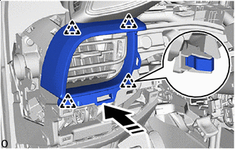
INSTALL FUSE BOX OPENING COVER (w/ Knee Airbag)
-
Connect each connector.
-
Install in this Direction Engage the clips to install the fuse box opening cover as shown in the illustration.
-
Install the screw <D> or screw <M>.
-
-
CONNECT HOOD LOCK CONTROL LEVER SUB-ASSEMBLY
-
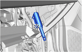
Install in this Direction Engage the guides and claw to connect the hood lock control lever sub-assembly as shown in the illustration.
-
-
INSTALL COMBINATION METER ASSEMBLY
-
INSTALL STARTER SWITCH BEZEL (for RHD with Entry and Start System)
-
Connect the connector.
-
Install in this Direction Engage the clips to install the starter switch bezel as shown in the illustration.
-
-
INSTALL NO. 2 INSTRUMENT PANEL GARNISH SUB-ASSEMBLY
-
Install in this Direction Engage the clips to install the No. 2 instrument panel garnish sub-assembly as shown in the illustration.
-
-
INSTALL INSTRUMENT CLUSTER FINISH PANEL ASSEMBLY
-
Install in this Direction Engage the guides and clips to install the instrument cluster finish panel assembly as shown in the illustration.
-
Install the 2 clips.
-
Install in this Direction Engage the claws to install the meter hood spacer as shown in the illustration.
-
-
INSTALL INSTRUMENT CLUSTER FINISH PANEL SUB-ASSEMBLY
-
w/ Switch:
-
Connect each connector.
-
-
Install in this Direction Engage the clips to install the instrument cluster finish panel sub-assembly as shown in the illustration.
-
-
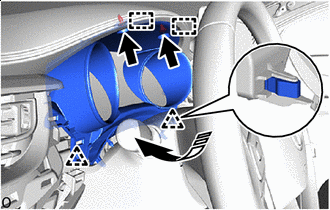
INSTALL NO. 2 FRONT SPEAKER ASSEMBLY (w/ Woofer)
-
INSTALL NO. 1 INSTRUMENT PANEL SPEAKER PANEL SUB-ASSEMBLY
-
w/ Speaker:
-
Connect the connector.
-
-
Install in this Direction (1) Install in this Direction (2) Engage the guides, claws and clips to install the No. 1 instrument panel speaker panel sub-assembly as shown in the illustration.
-
-
INSTALL NO. 2 INSTRUMENT PANEL SPEAKER PANEL SUB-ASSEMBLY
Tech Tips
Use the same procedure as for the No. 1 instrument panel speaker panel sub-assembly side.
-
INSTALL FRONT PILLAR GARNISH LH
-
*a Protective Cover 
Adhesive Tape Remove the adhesive tape and protective cover.
-
Install the 2 front pillar garnish clips to the front pillar garnish LH.
Note
-
If the front pillar garnish clip has significant damage, replace it with a new one.
-
When installing the front pillar garnish clip, make sure to install it in the correct position and facing in the correct direction.
-
-
w/ Speaker:
-
Connect the connector.
-
-
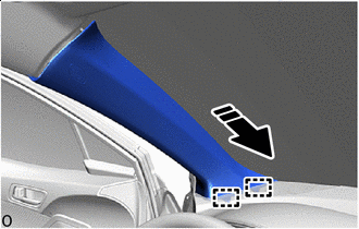
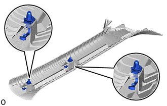
Install in this Direction Engage the guides as shown in the illustration.
-
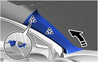
Install in this Direction Engage the clips to install the front pillar garnish LH as shown in the illustration.
-
-
INSTALL FRONT PILLAR GARNISH RH
Tech Tips
Use the same procedure as for the LH side.
-
INSTALL INSTRUMENT SIDE PANEL LH
-
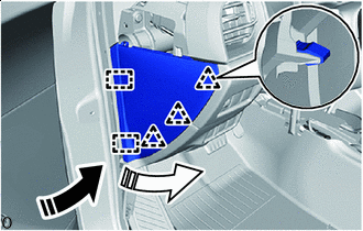
Install in this Direction (1) Install in this Direction (2) Engage the guides and clips to install the instrument side panel LH as shown in the illustration.
-
w/ Airbag Cut Off Switch:
-
Connect the connector.
-
-
-
INSTALL INSTRUMENT SIDE PANEL RH
Tech Tips
Use the same procedure as for the LH side.
-
INSTALL INSTRUMENT PANEL FINISH END PANEL LH
-
Install in this Direction (1) Install in this Direction (2) Engage the guides and clips to install the instrument panel finish end panel LH as shown in the illustration.
-
-
INSTALL INSTRUMENT PANEL FINISH END PANEL RH
Tech Tips
Use the same procedure as for the LH side.
-
CONNECT FRONT DOOR OPENING TRIM WEATHERSTRIP LH
-
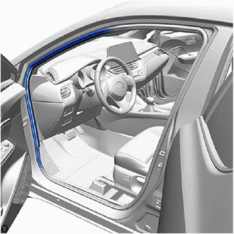
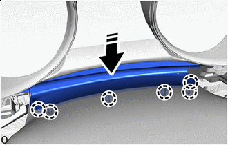
Connect the front door opening trim weatherstrip LH to the area shown in the illustration.
-
-
CONNECT FRONT DOOR OPENING TRIM WEATHERSTRIP RH
Tech Tips
Use the same procedure as for the LH side.
-
INSTALL NO. 2 INSTRUMENT PANEL LOWER FINISH PANEL
-
Connect the connector.
-
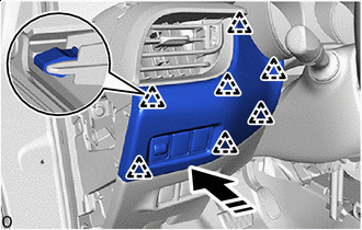
Install in this Direction Engage the clips and claws to install the No. 2 instrument panel lower finish panel as shown in the illustration.
-
Install the 5 screws <D> or 5 screws <M>.
-
-
INSTALL GLOVE COMPARTMENT DOOR STOPPER SUB-ASSEMBLY
-
Engage the claw to install the glove compartment door stopper sub-assembly.
-
-
INSTALL GLOVE COMPARTMENT DOOR ASSEMBLY
-
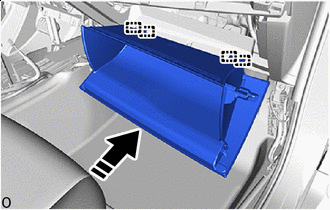
Install in this Direction With the glove compartment door assembly opened approximately 61° from its closed position, engage the 4 hinges horizontally.
Note
-
Engaging the hinges from the top will deform the hinges.
-
Be sure to install the glove compartment door assembly horizontally.
-
-
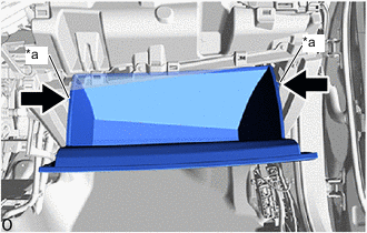
*a Stopper While pushing in the sides of the glove compartment door assembly as indicated by the arrows in the illustration, close the door to engage it to the 2 stoppers.
-
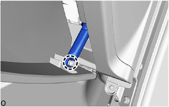
Engage the claw to connect the glove compartment door stopper sub-assembly.
-
-
INSTALL NO. 2 INSTRUMENT PANEL UNDER COVER SUB-ASSEMBLY
-
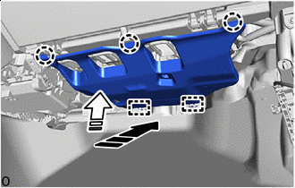
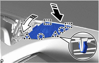
Install in this Direction (1) Install in this Direction (2) Engage the guides and claws to install the No. 2 instrument panel under cover sub-assembly as shown in the illustration.
-
-
INSTALL COWL SIDE TRIM BOARD RH
-
INSTALL FRONT DOOR SCUFF PLATE RH
-
INSTALL HEADLIGHT DIMMER SWITCH ASSEMBLY
-
INSTALL REAR CONSOLE BOX ASSEMBLY
-
CONNECT CABLE TO NEGATIVE BATTERY TERMINAL
-
for 8NR-FTS
-
for 3ZR-FAE
Note
When disconnecting the cable, some systems need to be initialized after the cable is reconnected.
-
-
INSPECT SRS WARNING LIGHT