BLOWER UNIT(for VALEO Made) REMOVAL
CAUTION / NOTICE / HINT
The necessary procedures (adjustment, calibration, initialization, or registration) that must be performed after parts are removed, installed, or replaced during the blower unit removal/installation are shown below.
| Replacement Part or Procedure | Necessary Procedures | Effects / Inoperative when not performed | Link |
|---|---|---|---|
| Disconnect cable from negative battery terminal | Memorize steering angle neutral point | Lane departure alert system (w/ Steering Control) | |
| Simple intelligent parking assist system*1 | |||
| Toyota parking assist-sensor system (w/ Simple Intelligent Parking Assist System)*1 | |||
| Pre-collision system | |||
| Initialize back door lock | Power door lock control system | ||
| Drive the vehicle until stop and start control is permitted (approximately 5 to 60 minutes)*2 | Stop and start system | ||
| No. 1 Blower Damper Servo Sub-assembly | Initialize servo motor (Air conditioning system) | DTCs are stored |
*1: When performing learning using the GTS.
*2: w/ Stop and start system
Tech Tips
-
Use the same procedure for RHD and LHD vehicles.
-
The procedure listed below is for LHD vehicles.
PROCEDURE
-
PRECAUTION
Note
Make sure to perform initialization after replacing the No. 1 blower damper servo sub-assembly. If initialization is not performed, the air conditioner unit assembly will not perform properly as the air conditioning amplifier assembly will not be able to recognize the position of the No. 1 blower damper servo sub-assembly.
-
REMOVE AIR CONDITIONER UNIT ASSEMBLY
-
REMOVE NO. 2 AIR DUCT (for LHD)
-
REMOVE NO. 1 AIR DUCT (for RHD)
-
REMOVE NO. 3 INSTRUMENT PANEL WIRE (w/ PTC Heater)
-
REMOVE BLOWER ASSEMBLY
-
for LHD:
-
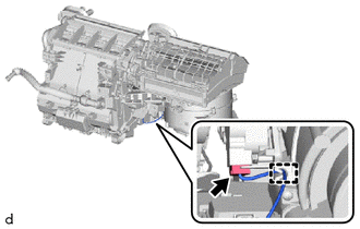
Disconnect the connector.
-
Disengage the guide.
-
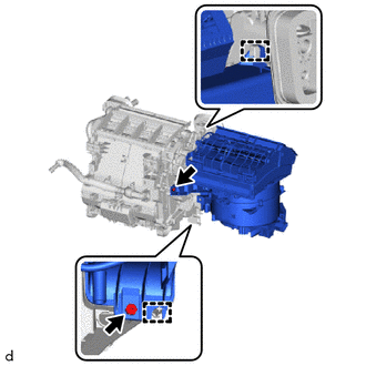
Remove the 2 screws.
-
Disengage the guides to remove the blower assembly from the air conditioning radiator assembly.
-
-
for RHD:
-
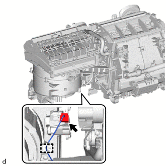
Disconnect the connector.
-
Disengage the guide.
-
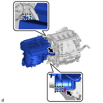
Remove the 2 screws.
-
Disengage the guides to remove the blower assembly from the air conditioning radiator assembly.
-
-