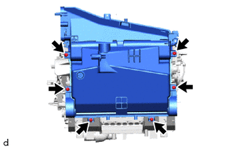
AIR CONDITIONING UNIT(for VALEO Made) REASSEMBLY
Info Added 2017-10-06 ![]()
CAUTION / NOTICE / HINT
Tech Tips
-
Use the same procedure for RHD and LHD vehicles.
-
The procedure listed below is for LHD vehicles.
PROCEDURE
-
INSTALL NO. 1 COOLER THERMISTOR
-
INSTALL NO. 2 RADIATOR CASE SUB-ASSEMBLY
-
Install the No. 2 radiator case sub-assembly with the 6 screws.
-
-
INSTALL NO. 1 COOLER EVAPORATOR SUB-ASSEMBLY
-

Install in this Direction Install the No. 1 cooler evaporator sub-assembly with No. 1 cooler thermistor as shown in the illustration.
-
Connect the the connector.
-
-
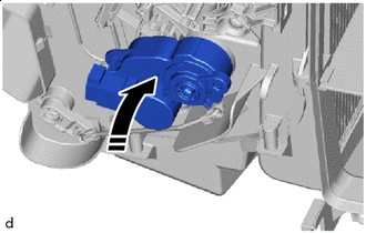
INSTALL RADIATOR CASE SUB-ASSEMBLY
-
Engage the claws and to install the radiator case sub-assembly.
-
Install the 3 screws.
-
-
INSTALL HEAT EXCHANGER CASE
-
Engage the 2 claws and guide, and install the heat exchanger case with the screw.
-
Install the bracket with the 2 screws.
-
-
INSTALL COOLER EXPANSION VALVE
-
Install the grommet.
-
Sufficiently apply compressor oil to 2 new O-rings and fitting surfaces of the No. 1 cooler evaporator sub-assembly.
Compressor Oil VC100YF or equivalent -
Install the 2 O-rings to the No. 1 cooler evaporator sub-assembly.
Note
Keep the O-rings and O-ring fitting surfaces free of foreign matter.
-
Using a 4 mm hexagon socket wrench, install the cooler expansion valve with the 2 hexagon bolts.
- Torque:
- 4.5 N*m { 46 kgf*cm, 40 in.*lbf }
-
-
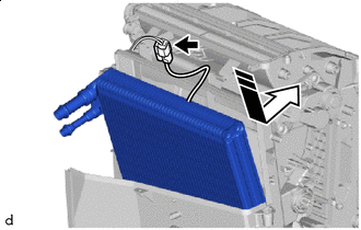
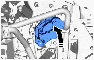
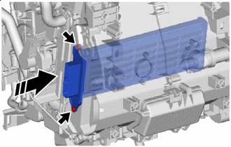
INSTALL HEATER RADIATOR UNIT SUB-ASSEMBLY
-
Install in this Direction Install the heater radiator unit sub-assembly as shown in the illustration.
-
Install the 3 screws.
-
-
INSTALL HEATER CLAMP
-
Engage the claws to install the heater clamp.
-
Install the screw.
-
-
INSTALL HEATER PIPE GROMMET
-
Install the heater pipe grommet.
-
-
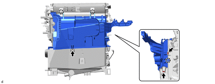
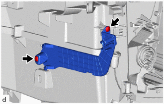
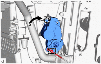
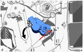
INSTALL NO. 2 AIR CONDITIONING RADIATOR DAMPER SERVO SUB-ASSEMBLY
-
Install in this Direction Install the No. 2 air conditioning radiator damper servo sub-assembly as shown in the illustration.
-
Install in this Direction Turn the No. 2 air conditioning radiator damper servo sub-assembly to engage the claw as shown in the illustration.
-
-
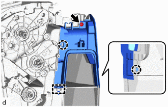
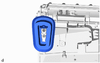
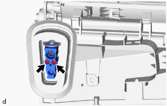
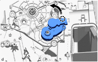
INSTALL NO. 1 AIR CONDITIONING RADIATOR DAMPER SERVO SUB-ASSEMBLY (for Automatic Air Conditioning System)
-
for Lower RH Side:
-

Install in this Direction Install the No. 1 air conditioning radiator damper servo sub-assembly as shown in the illustration.
-
Install in this Direction Turn the No. 1 air conditioning radiator damper servo sub-assembly to engage the claw as shown in the illustration.
-
Engage the snap.
-
-
for Upper RH Side:
-
Install in this Direction Install the No. 1 air conditioning radiator damper servo sub-assembly as shown in the illustration.
-

Install in this Direction Turn the No. 1 air conditioning radiator damper servo sub-assembly to engage the claw as shown in the illustration.
-
-
for Lower LH Side:
-
Install in this Direction Install the No. 1 air conditioning radiator damper servo sub-assembly as shown in the illustration.
-
Install in this Direction Turn the No. 1 air conditioning radiator damper servo sub-assembly to engage the claw as shown in the illustration.
-
Engage the snap.
-
-
for Upper LH Side:
-
Install in this Direction Install the No. 1 air conditioning radiator damper servo sub-assembly as shown in the illustration.
-
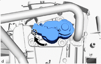
Install in this Direction Turn the No. 1 air conditioning radiator damper servo sub-assembly to engage the claw as shown in the illustration.
-
-
-
INSTALL NO. 1 AIR CONDITIONING RADIATOR DAMPER SERVO SUB-ASSEMBLY (for Manual Air Conditioning System)
-
for Lower RH Side:
-
Install in this Direction Install the No. 1 air conditioning radiator damper servo sub-assembly as shown in the illustration.
-
Install in this Direction Turn the No. 1 air conditioning radiator damper servo sub-assembly to engage the claw as shown in the illustration.
-
Engage the snap.
-
-
for Upper RH Side:
-

Install in this Direction Install the No. 1 air conditioning radiator damper servo sub-assembly as shown in the illustration.
-
Install in this Direction Turn the No. 1 air conditioning radiator damper servo sub-assembly to engage the claw as shown in the illustration.
-
-
-
INSTALL NO. 2 COOLER UNIT DRAIN HOSE
-
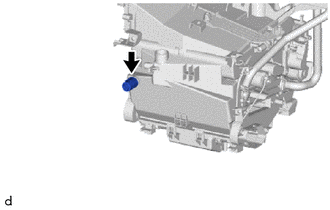
Install the No. 2 cooler unit drain hose.
-
-
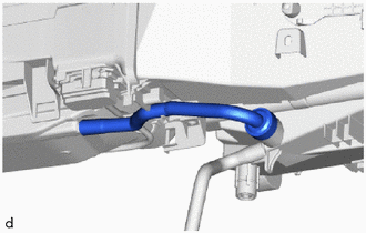
INSTALL DRAIN COOLER HOSE
-
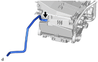
Install the drain cooler hose.
-
-
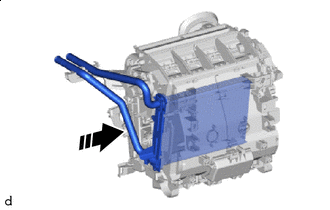
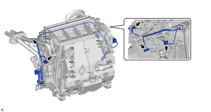
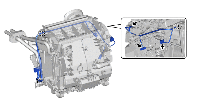
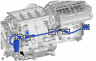
INSTALL AIR CONDITIONING HARNESS ASSEMBLY
-
for Automatic Air Conditioning System:
-
Engage clamps to install the air conditioning harness assembly.
-
Connect the 5 connectors.
-
-
for Manual Air Conditioning System:
-
Engage clamps to install the air conditioning harness assembly.
-
Connect the 3 connectors.
-
-
-
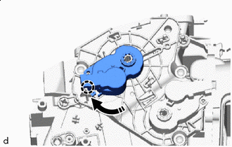
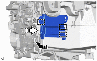
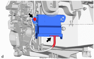
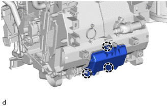
INSTALL AIR CONDITIONING AMPLIFIER ASSEMBLY
-
for LHD:
-
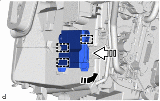
Install in this Direction (1) 
Install in this Direction (2) Engage the guides to temporarily install the air conditioning amplifier assembly as shown in the illustration.
-
Install the air conditioning amplifier assembly with the screw.
-
Connect the connector.
-
-
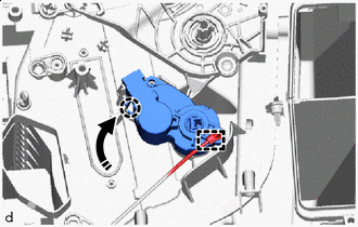
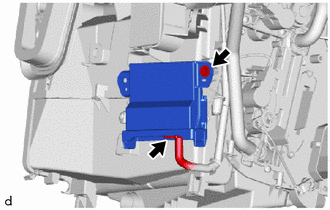
for RHD:
-
Install in this Direction (1) Install in this Direction (2) Engage the guides to temporarily install the air conditioning amplifier assembly as shown in the illustration.
-
Install the air conditioning amplifier assembly with the screw.
-
Connect the connector.
-
-
-
INSTALL HEATER COVER (w/o PTC Heater)
-

Install in this Direction Install the heater cover with the 2 screws as shown in the illustration.
-
-
INSTALL QUICK HEATER ASSEMBLY (w/ PTC Heater)
-
Install in this Direction Install the quick heater assembly with the 2 screws as shown in the illustration.
-
-
INSTALL NO. 2 HEATER COVER (w/ PTC Heater)
-
Remove the No. 2 heater cover with the screw.
-
-
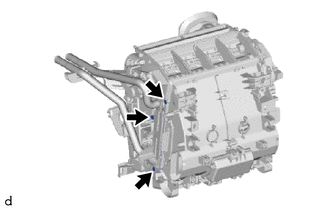
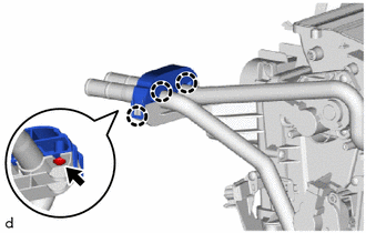
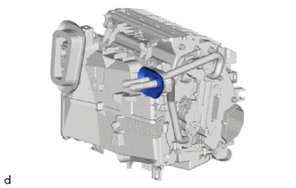
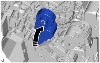
INSTALL BLOWER ASSEMBLY
-
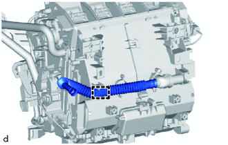
INSTALL NO. 3 COOLER UNIT DRAIN HOSE
-
Install the No. 3 cooler unit drain hose.
-
-
INSTALL NO. 3 INSTRUMENT PANEL WIRE (w/ PTC Heater)
-
Engage the clamps to install the No. 3 instrument panel wire.
-
Connect the connector.
-
-
INSTALL COVER (w/o Rear Air Duct)
-
Engage the claws to install the cover.
-
-
INSTALL AIR CONDITIONING DUCT SUB-ASSEMBLY
-
Engage the guide to install the air conditioning duct sub-assembly.
-
-
INSTALL NO. 2 AIR DUCT (for LHD)
-
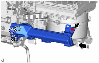
Install in this Direction Engage the claws to install the No. 2 air duct as shown in the illustration.
-
Install the screw.
-
-
INSTALL NO. 1 AIR DUCT (for RHD)
-
Install in this Direction Engage the claws to install the No. 1 air duct as shown in the illustration.
-
Install the screw.
-