AIR CONDITIONING UNIT(for VALEO Made) REMOVAL
Info Added 2017-10-06 ![]()
CAUTION / NOTICE / HINT
The necessary procedures (adjustment, calibration, initialization, or registration) that must be performed after parts are removed, installed, or replaced during the air conditioner unit assembly removal/installation are shown below.
| Replacement Part or Procedure | Necessary Procedures | Effects / Inoperative when not performed | Link |
|---|---|---|---|
| Disconnect cable from negative battery terminal | Memorize steering angle neutral point | Lane departure alert system (w/ Steering Control) | |
| Simple intelligent parking assist system*1 | |||
| Toyota parking assist-sensor system (w/ Simple Intelligent Parking Assist System)*1 | |||
| Pre-collision system | |||
| Initialize back door lock | Power door lock control system | ||
| Drive the vehicle until stop and start control is permitted (approximately 5 to 60 minutes)*2 | Stop and start system | ||
|
Initialize servo motor (Air conditioning system) | DTCs are stored |
*1: When performing learning using the GTS.
*2: w/ Stop and start system
Tech Tips
-
Use the same procedure for RHD and LHD vehicles.
-
The procedure listed below is for LHD vehicles.
PROCEDURE
-
RECOVER REFRIGERANT FROM REFRIGERATION SYSTEM (for HFC-134a(R134a))
-
RECOVER REFRIGERANT FROM REFRIGERATION SYSTEM (for HFO-1234yf(R1234yf))
-
DRAIN ENGINE COOLANT (for 8NR-FTS)
-
DRAIN ENGINE COOLANT (for 3ZR-FAE)
-
REMOVE WINDSHIELD WIPER MOTOR AND LINK ASSEMBLY
-
REMOVE NO. 1 HEATER AIR DUCT SPLASH SHIELD SEAL
-
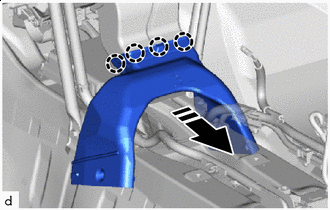
REMOVE WATER GUARD PLATE LH
-
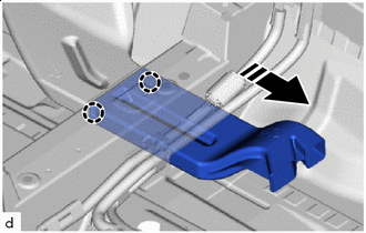
REMOVE COWL BODY MOUNTING REINFORCEMENT LH
-
REMOVE COWL BODY MOUNTING REINFORCEMENT RH
-
REMOVE OUTER COWL TOP PANEL SUB-ASSEMBLY (for LHD)
-
REMOVE OUTER COWL TOP PANEL SUB-ASSEMBLY (for RHD)
-
DISCONNECT OUTLET HEATER WATER HOSE
-
Slide the hose clip to disconnect the outlet heater water hose.
Note
-
To prevent contamination by foreign matter or water droplets, protect the connecting portions of the outlet heater water hose and air conditioner radiator assembly with plastic bags.
-
Do not apply excessive force to the outlet heater water hose.
-
Prepare a drain pan or cloth in case the coolant leaks.
-
-
-
DISCONNECT INLET HEATER WATER HOSE
-
Slide the hose clip to disconnect the inlet heater water hose.
Note
-
To prevent contamination by foreign matter or water droplets, protect the connecting portions of the inlet heater water hose and air conditioner radiator assembly with plastic bags.
-
Do not apply excessive force to the inlet heater water hose.
-
Prepare a drain pan or cloth in case the coolant leaks.
-
-
-
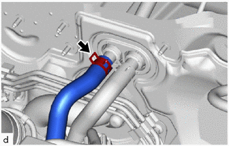
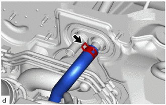
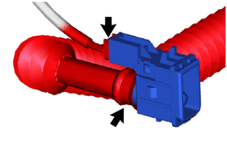
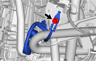
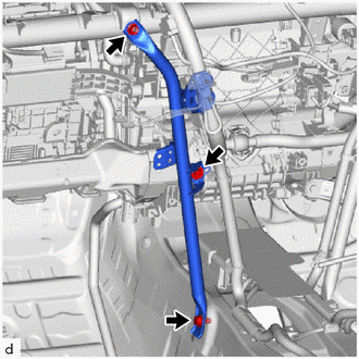
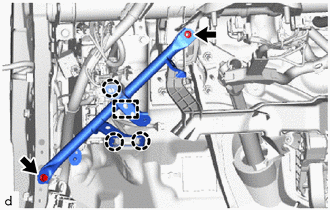
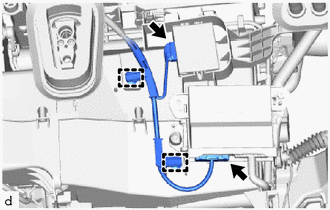
DISCONNECT SUCTION PIPE SUB-ASSEMBLY
-
Remove the bolt.
-
Disconnect the suction pipe sub-assembly and cooler refrigerant liquid pipe A shown in the illustration.
-
Remove the 2 O-rings from the suction pipe sub-assembly and cooler refrigerant liquid pipe A.
Note
Seal the openings of the disconnected parts using vinyl tape to prevent entry of moisture and foreign matter.
-
-
REMOVE FRONT SEAT ASSEMBLY LH
-
REMOVE FRONT SEAT ASSEMBLY RH
Tech Tips
Use the same procedure as for the LH side.
-
REMOVE INSTRUMENT PANEL SAFETY PAD SUB-ASSEMBLY
-
REMOVE STEERING COLUMN ASSEMBLY
-
REMOVE WINDSHIELD WIPER RELAY ASSEMBLY
-
REMOVE CLEARANCE WARNING ECU ASSEMBLY (w/ Clearance Sonar System)
-
REMOVE ECU INTEGRATION BOX RH (for LHD)
-
REMOVE ECU INTEGRATION BOX LH (for RHD)
-
REMOVE COOLER THERMISTOR (ROOM TEMPERATURE SENSOR)
-
Disconnect the connector and air conditioning duct sub-assembly to remove the cooler thermistor (room temperature sensor).
-
-
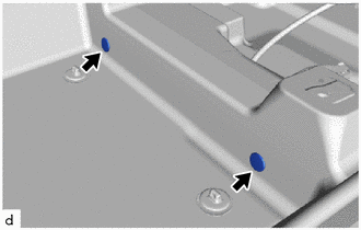
REMOVE NO. 3 DASH PANEL INSULATOR PAD
-
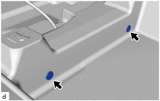
Remove the 2 front floor carpet clips.
-

Remove in this Direction Remove the clip.
-
Disengage the clamps to turn back the front floor carpet assembly as shown in the illustration.
-
Disengage the clips to remove the No. 3 dash panel insulator pad.
-
-
REMOVE REAR NO. 6 AIR DUCT (w/ Rear Air Duct)
-
Remove in this Direction Disengage the claws to remove the rear No. 6 air duct as shown in the illustration.
-
-
REMOVE REAR NO. 5 AIR DUCT (w/ Rear Air Duct)
-
Remove in this Direction Disengage the claws to remove the rear No. 5 air duct as shown in the illustration.
-
-
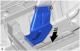
REMOVE REAR NO. 4 AIR DUCT (w/ Rear Air Duct)
-
Remove the 2 front floor carpet clips.
-
Remove in this Direction Remove the clip.
-
Disengage the clamps to turn back the front floor carpet assembly as shown in the illustration.
-
Remove in this Direction Disengage the claws to remove the rear No. 4 air duct as shown in the illustration.
-
-
REMOVE REAR NO. 3 AIR DUCT (w/ Rear Air Duct)
-
Remove in this Direction Disengage the claws to remove the rear No. 3 air duct as shown in the illustration.
-
-
REMOVE REAR NO. 2 AIR DUCT (w/ Rear Air Duct)
-
Remove in this Direction Disengage the claws to remove the rear No. 2 air duct.
-
-
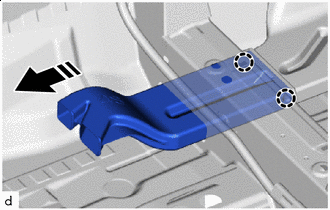
REMOVE REAR NO. 1 AIR DUCT (w/ Rear Air Duct)
-
Remove in this Direction Disengage the claws to remove the rear No. 1 air duct as shown in the illustration.
-
-
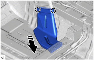
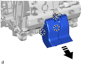
REMOVE NO. 1 INSTRUMENT PANEL BRACE SUB-ASSEMBLY
-
w/ PTC Heater:
-
Remove the bolt to disconnect the ground wire.
-
-
Remove the 2 nuts and separate the relay block assembly.
-
for LHD:
-
Disengage the clamps to disconnect the wire harness.
-
Remove the bolt, screw, nut and No. 1 instrument panel brace sub-assembly.
-
-
for RHD:
-
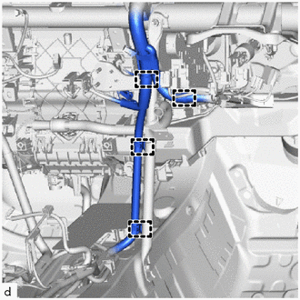
Disengage the clamps to disconnect the wire harness.
-
Remove the bolt, screw, nut and No. 1 instrument panel brace sub-assembly.
-
-
-
REMOVE NO. 2 INSTRUMENT PANEL BRACE SUB-ASSEMBLY
-
for LHD:
-
Remove the bolt to disconnect the ground wire.
-
Disengage the clamps to disconnect the wire harness.
-
Remove the bolt, screw, nut and No. 2 instrument panel brace sub-assembly.
-
-
for RHD:
-
Remove the bolt to disconnect the ground wire.
-
Disengage the clamps to disconnect the wire harness.
-
Remove the bolt, screw, nut and No. 2 instrument panel brace sub-assembly.
-
-
-
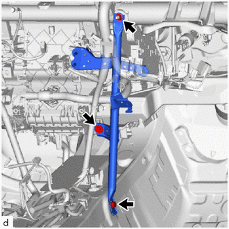
REMOVE NO. 3 INSTRUMENT PANEL TO COWL BRACE SUB-ASSEMBLY
-
Disengage the clamp and claws.
-
Remove the bolt, nut and No. 3 instrument panel to cowl brace sub-assembly.
-
-
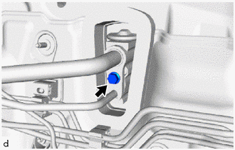
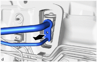
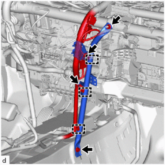
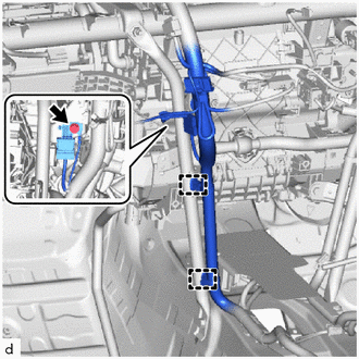
REMOVE DRAIN COOLER HOSE
-
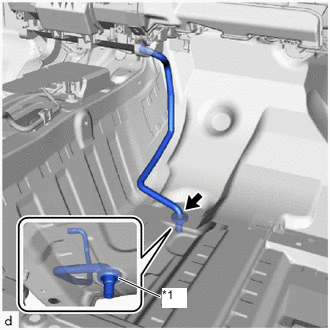
*1 Cooler Unit Drain Hose Grommet Disconnect the drain cooler hose.
Note
If the cooler unit drain hose grommet is disconnected from the vehicle body while disconnecting the drain cooler hose, make sure to replace it with a new one. Failure to do so may cause water ingress.
-
-
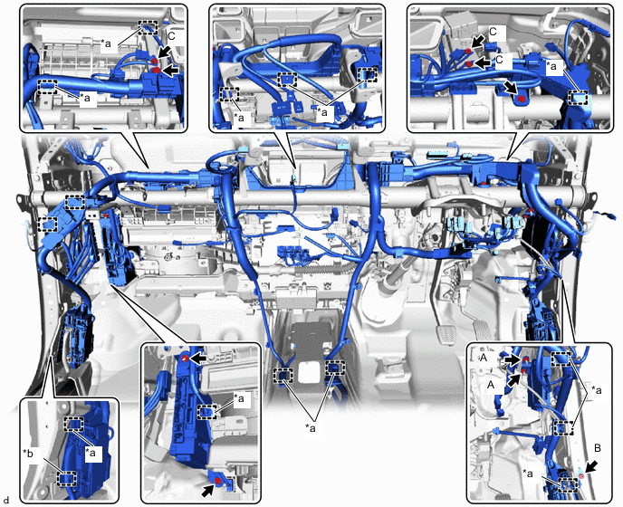
DISCONNECT INSTRUMENT PANEL WIRE
-
for LHD:
-
Disconnect each connector.
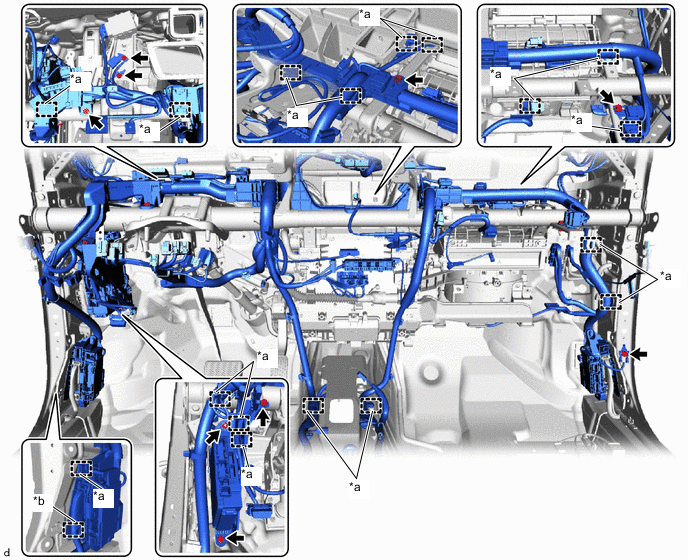
*a Clamp *b Hook -
Remove the bolt and screw.
-
Remove the 4 bolts to disconnect the 4 ground wires.
-
Remove the bolt and nut to separate the instrument panel junction block assembly with main body ECU.
-
Disengage clamps and hook to disconnect the instrument panel wire.
-
-
for RHD:
-
Disconnect each connector.
*a Clamp *b Hook -
Remove the bolt and screw.
-
Remove the 4 bolts to disconnect the 4 ground wires.
-
Remove the 2 nuts A.
-
Remove the bolt and nut to separate the instrument panel junction block assembly with main body ECU.
-
Disengage clamps and hook to disconnect the instrument panel wire.
-
-
-
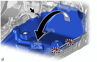
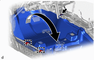
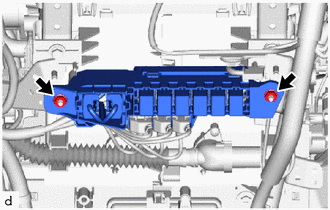
REMOVE INSTRUMENT PANEL REINFORCEMENT ASSEMBLY WITH AIR CONDITIONER UNIT ASSEMBLY
Note
-
Be sure to support the air conditioner unit assembly when removing it. Failure to do so may cause the bracket of the air conditioner unit assembly to break.
-
When disassembling the air conditioner unit assembly, eliminate static electricity by touching the vehicle body to prevent the components from being damaged.
-
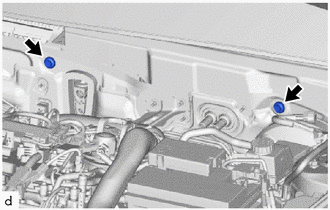
Remove the 2 bolts.
-
Remove the 5 bolts.
-
Remove the nut.
-
Disengage the clamps.
-
Disconnect 2 connectors.
-
Disengage the guides to remove the instrument panel reinforcement assembly with air conditioner unit assembly as shown in the illustration.
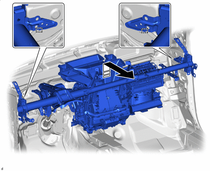
Remove in this Direction - -
-
-
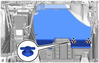
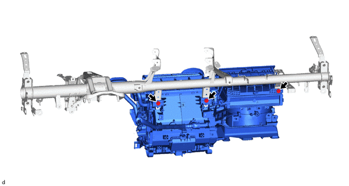
REMOVE AIR CONDITIONER UNIT ASSEMBLY
-
Remove the 3 bolts and air conditioner unit assembly from the instrument panel reinforcement assembly.
-
-
REMOVE LOWER DEFROSTER NOZZLE ASSEMBLY
-
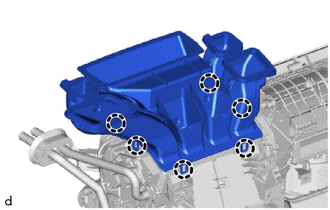
Disengage the claws to remove the lower defroster nozzle assembly.
-