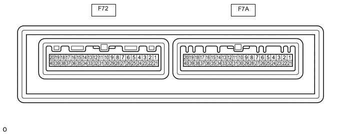
AIR CONDITIONING SYSTEM(for Manual Air Conditioning System) TERMINALS OF ECU
-
AIR CONDITIONING AMPLIFIER ASSEMBLY
Tech Tips
Check from the rear of the connector while it is connected to the air conditioning amplifier assembly.
Terminal No. (symbol) Wiring Color Terminal Description Condition Specified Condition F72-1 (B) - Body ground V - Body ground Power source (Back-up) Always 11 to 14 V F72-3 (LIN1) - F72-29 (GND) L - W-B*3
BE - W-B*4
LIN communication signal (Air conditioning control assembly) Ignition switch ON Pulse generation
(See waveform 1)
F72-5 (IG+) - Body ground B - Body ground Power Source (IG) Ignition switch ON 11 to 14 V Ignition switch off Below 1 V F72-9 (CANH) - F72-10 (CANL) P - SB CAN communication CAN communication is performed Pulse generation F72-15 (SOL-) - F72-29 (GND)*7 L - W-B Compressor solenoid operation
-
Engine running
-
Blower switch: Lo
-
A/C switch: On
Pulse generation
(See waveform 2)
F72-19 (PTC1) - F72-29 (GND)*1 L - W-B Output for driving PTC1 heater relay
-
Ignition switch ON
-
ECO mode: off
-
Temperature setting: MAX HOT
-
Ambient temperature: 25°C (77°F) or lower
-
Engine coolant temperature: 75°C (167°F) or lower
-
Light control switch off
-
Blower switch: Lo
Below 1 V
-
Ignition switch ON
-
ECO mode: off
-
Temperature setting: MAX HOT
-
Ambient temperature: 25°C (77°F) or lower
-
Engine coolant temperature: 75°C (167°F) or lower
-
Light control switch off
-
Blower switch: Off
11 to 14 V F72-20 (PTC3) - F72-29 (GND)*1 BR - W-B Output for driving PTC3 heater relay
-
Ignition switch ON
-
ECO mode: off
-
Temperature setting: MAX HOT
-
Ambient temperature: -7°C (19°F) or lower
-
Engine coolant temperature: 65°C (149°F) or lower
-
Light control switch off
-
Blower switch: Lo
Below 1 V
-
Ignition switch ON
-
ECO mode: off
-
Temperature setting: MAX HOT
-
Ambient temperature: -7°C (19°F) or lower
-
Engine coolant temperature: 65°C (149°F) or lower
-
Light control switch off
-
Blower switch: Off
11 to 14 V F72-29 (GND) - Body ground W-B - Body ground Ground for main power supply Always Below 1 V F72-32 (SG-2) - Body ground*7 G - Body ground Ground for air conditioner pressure sensor Always Below 1 V F72-33 (PRE) - F72-32 (SG-2)*5,*7 V - G Input from refrigerant gas sensor
-
Ignition switch ON
-
Air conditioning system operating
-
Refrigerant pressure: Abnormal pressure (more than 3025 kPa (30.8 kgf/cm2, 439 psi))
4.61 V or higher
-
Ignition switch ON
-
Air conditioning system operating
-
Refrigerant pressure: Abnormal pressure (less than 176 kPa (1.8 kgf/cm2, 26 psi))
Below 0.74 V
-
Ignition switch ON
-
Air conditioning system operating
-
Refrigerant pressure: Normal pressure (less than 3025 kPa (30.8 kgf/cm2, 439 psi) and more than 176 kPa (1.8 kgf/cm2, 26 psi))
0.74 to 4.61 V F72-33 (PRE) - F72-32 (SG-2)*6,*7 V - G Input from refrigerant gas sensor
-
Ignition switch ON
-
Air conditioning system operating
-
Refrigerant pressure: Abnormal pressure (more than 2812 kPa (28.7 kgf/cm2, 408 psi))
4.61 V or higher
-
Ignition switch ON
-
Air conditioning system operating
-
Refrigerant pressure: Abnormal pressure (less than 195 kPa (2.0 kgf/cm2, 28 psi))
Below 0.74 V
-
Ignition switch ON
-
Air conditioning system operating
-
Refrigerant pressure: Normal pressure (less than 2812 kPa (28.7 kgf/cm2, 408 psi) and more than 195 kPa (2.0 kgf/cm2, 28 psi))
0.74 to 4.61 V F72-34 (S5-3) - F72-32 (SG-2)*7 GR - G Power supply for air conditioner pressure sensor Ignition switch ON 4.75 to 5.25 V Ignition switch off Below 1 V F72-39 (PTC2) - F72-29 (GND)*1 V - W-B Output for driving PTC2 heater relay
-
Ignition switch ON
-
ECO mode: off
-
Temperature setting: MAX HOT
-
Ambient temperature: 16°C (61°F) or lower
-
Engine coolant temperature: 70°C (158°F) or lower
-
Light control switch off
-
Blower switch: Lo
Below 1 V
-
Ignition switch ON
-
ECO mode: off
-
Temperature setting: MAX HOT
-
Ambient temperature: 16°C (61°F) or lower
-
Engine coolant temperature: 70°C (158°F) or lower
-
Light control switch off
-
Blower switch: Off
11 to 14 V F7A-1 (SHUNT1) - Body ground - Set HVAC double layer
-
Ignition switch ON
-
Double Layer*2
11 to 14 V
-
Ignition switch ON
-
Single Layer
Below 1 V F7A-2 (B2AI) - Body ground - Output for driving the motor to switch inlet/outlet B2
-
Ignition switch ON
-
No. 1 blower damper servo sub-assembly (fresh/recirculation) operating
Pulse generation
(See waveform 3)
F7A-3 (A2AI) - Body ground - Output for driving the motor to switch inlet/outlet A2
-
Ignition switch ON
-
No. 1 blower damper servo sub-assembly (fresh/recirculation) operating
Pulse generation
(See waveform 3)
F7A-4 (A2AO) - Body ground - Output for driving the motor to switch mode A2
-
Ignition switch ON
-
No. 2 air conditioning radiator damper servo sub-assembly (mode switching) operating
Pulse generation
(See waveform 4)
F7A-6 (B2AO) - Body ground - Output for driving the motor to switch mode B2
-
Ignition switch ON
-
No. 2 air conditioning radiator damper servo sub-assembly (mode switching) operating
Pulse generation
(See waveform 4)
F7A-8 (B1AO) - Body ground - Output for driving the motor to switch mode B1
-
Ignition switch ON
-
No. 2 air conditioning radiator damper servo sub-assembly (mode switching) operating
Pulse generation
(See waveform 4)
F7A-9 (A1AI) - Body ground - Output for driving the motor to switch inlet/outlet A1
-
Ignition switch ON
-
No. 1 blower damper servo sub-assembly (fresh/recirculation) operating
Pulse generation
(See waveform 3)
F7A-10 (B1AI) - Body ground - Output for driving the motor to switch inlet/outlet B1
-
Ignition switch ON
-
No. 1 blower damper servo sub-assembly (fresh/recirculation) operating
Pulse generation
(See waveform 3)
F7A-13 (BAI) - Body ground - Power supply to the motor to switch inlet/outlet Ignition switch ON 11 to 14 V F7A-16 (A1AO) - Body ground - Output for driving the motor to switch mode A1
-
Ignition switch ON
-
No. 2 air conditioning radiator damper servo sub-assembly (mode switching) operating
Pulse generation
(See waveform 4)
F7A-21 (SHUNT2) - Body ground - Set HVAC double layer
-
Ignition switch ON
-
Double Layer*2
11 to 14 V
-
Ignition switch ON
-
Single Layer
Below 1 V F7A-22 (B1RU) - Body ground - Output for driving the air mix motor in right upper layer B1
-
Ignition switch ON
-
No. 1 air conditioning radiator damper servo sub-assembly (upper air mix) operating
Pulse generation
(See waveform 5)
F7A-23 (A2RL) - Body ground - Output for driving the air mix motor in right lower layer A2
-
Ignition switch ON
-
No. 1 air conditioning radiator damper servo sub-assembly (lower air mix) operating
Pulse generation
(See waveform 6)
F7A-24 (A1RU) - Body ground - Output for driving the air mix motor in right upper layer A1
-
Ignition switch ON
-
No. 1 air conditioning radiator damper servo sub-assembly (upper air mix) operating
Pulse generation
(See waveform 5)
F7A-25 (B2RL) - Body ground - Output for driving the air mix motor in right lower layer B2
-
Ignition switch ON
-
No. 1 air conditioning radiator damper servo sub-assembly (lower air mix) operating
Pulse generation
(See waveform 6)
F7A-26 (B1RL) - Body ground - Output for driving the air mix motor in right lower layer B1
-
Ignition switch ON
-
No. 1 air conditioning radiator damper servo sub-assembly (lower air mix) operating
Pulse generation
(See waveform 6)
F7A-27 (A2RU) - Body ground - Output for driving the air mix motor in right upper layer A2
-
Ignition switch ON
-
No. 1 air conditioning radiator damper servo sub-assembly (upper air mix) operating
Pulse generation
(See waveform 5)
F7A-28 (A1RL) - Body ground - Output for driving the air mix motor in right lower layer A1
-
Ignition switch ON
-
No. 1 air conditioning radiator damper servo sub-assembly (lower air mix) operating
Pulse generation
(See waveform 6)
F7A-29 (B2RU) - Body ground - Output for driving the air mix motor in right upper layer B2
-
Ignition switch ON
-
No. 1 air conditioning radiator damper servo sub-assembly (upper air mix) operating
Pulse generation
(See waveform 5)
F7A-32 (BAO) - Body ground - Power supply to the motor to switch mode Ignition switch ON 11 to 14 V F7A-33 (BRU) - Body ground - Power supply to the air mix motor in right upper layer Ignition switch ON 11 to 14 V F7A-34 (BRL) - Body ground - Power supply to the air mix motor in right lower layer Ignition switch ON 11 to 14 V F7A-38 (TEA) - F7A-39 (SGA) - Input No. 1 cooler thermistor
-
Ignition switch ON
-
Evaporator temperature: 0°C (32°F)
0.5 V
-
Ignition switch ON
-
Evaporator temperature: 25°C (77°F)
1.6 V F7A-39 (SGA) - Body ground - Ground for No. 1 cooler thermistor Always Below 1 V F7A-40 (BLW) - F72-29 (GND) - Output for driving Blower motor
-
Ignition switch ON
-
Blower switch: Lo
Pulse generation
(See waveform 4)
-
*1: w/ PTC Heater
-
*2: w/ Headlight Cleaner System
-
*3: for LHD
-
*4: for RHD
-
*5: for HFC-134a (R134a)
-
*6: for HFO-1234yf (R1234yf)
-
*7: w/ Cooler System
-
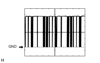
Waveform 1:
Item Content Terminal No. F72-3 (LIN1) - F72-29 (GND) Tool Setting 2 V/DIV., 20 ms./DIV. Vehicle Condition Ignition switch ON -

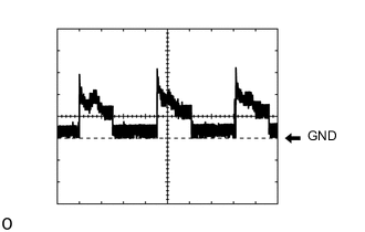
Waveform 2:
Item Content Terminal No. F72-15 (SOL-) - F72-29 (GND) Tool Setting 5 V/DIV., 1 ms./DIV. Vehicle Condition
-
Engine running
-
Blower switch: Lo
-
A/C switch: On
-
-

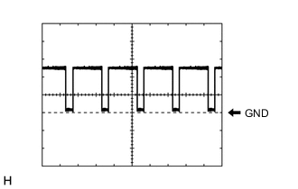
Waveform 3:
Item Content Terminal No. F7A-2 (B2AI) - Body ground F7A-3 (A2AI) - Body ground F7A-9 (A1AI) - Body ground F7A-10 (B1AI) - Body ground Tool Setting 2 V/DIV., 10 ms./DIV. Vehicle Condition
-
Ignition switch ON
-
No. 1 blower damper servo sub-assembly (fresh/recirculation) operating
-
-

Waveform 4:
Item Content Terminal No. F7A-4 (A2AO) - Body ground F7A-6 (B2AO) - Body ground F7A-8 (B1AO) - Body ground F7A-16 (A1AO) - Body ground Tool Setting 2 V/DIV., 10 ms./DIV. Vehicle Condition
-
Ignition switch ON
-
No. 2 air conditioning radiator damper servo sub-assembly (mode switching) operating
-
-
Waveform 5:
Item Content Terminal No. F7A-22 (B1RU) - Body ground F7A-24 (A1RU) - Body ground F7A-27 (A2RU) - Body ground F7A-29 (B2RU) - Body ground Tool Setting 2 V/DIV., 10 ms./DIV. Vehicle Condition
-
Ignition switch ON
-
No. 1 air conditioning radiator damper servo sub-assembly (upper air mix) operating (for LHD)
-
-

Waveform 6:
Item Content Terminal No. F7A-23 (A2RL) - Body ground F7A-25 (B2RL) - Body ground F7A-26 (B1RL) - Body ground F7A-28 (A1RL) - Body ground Tool Setting 2 V/DIV., 10 ms./DIV. Vehicle Condition
-
Ignition switch ON
-
No. 1 air conditioning radiator damper servo sub-assembly (lower air mix) operating (for LHD)
-
-
Waveform 7:
Item Content Terminal No. F7A-40 (BLW) - F72-29 (GND) Tool Setting 2 V/DIV., 1 ms./DIV. Vehicle Condition
-
Ignition switch ON
-
Blower switch: Lo
-
-
-
AIR CONDITIONING CONTROL ASSEMBLY

Tech Tips
Check from the rear of the connector while it is connected to the air conditioning control assembly.
Terminal No. (symbol) Wiring Color Terminal Description Condition Specified Condition F61-2 (LIN1) - Body ground L - Body ground LIN communication Ignition switch ON Pulse generation (See waveform 1) F61-10 (IG+) - Body ground BE - Body ground Power source (IG) Ignition switch off Below 1 V Ignition switch ON 11 to 14 V F61-16 (GND) - Body ground W-B - Body ground Ground for air conditioning control assembly Always Below 1 V
-

Waveform 1:
Item Content Terminal No. F61-2 (LIN1) - Body ground Tool Setting 2 V/DIV., 20 ms./DIV. Vehicle Condition Ignition switch ON
-