AIR CONDITIONING SYSTEM(for Automatic Air Conditioning System with Top-mounted Air Conditioner Pressure Sensor), Diagnostic DTC:B1451
| DTC Code | DTC Name |
|---|---|
| B1451 | Compressor Solenoid Circuit |
DESCRIPTION
In this circuit, the compressor with pulley assembly (compressor solenoid) receives a refrigerant compression demand signal from the air conditioning amplifier assembly.
Based on this signal, the compressor with pulley assembly (compressor solenoid) changes the amount of compressor output.
| DTC No. | Detection Item | DTC Detection Condition | Trouble Area | Memory |
|---|---|---|---|---|
| B1451 | Compressor Solenoid Circuit | Any of the following conditions is met:
|
|
- |
| Vehicle Condition | |||
|---|---|---|---|
| Pattern 1 | Pattern 2 | ||
| Diagnosis Condition | Ignition switch ON | ○ | ○ |
| Malfunction Status | Open in compressor solenoid circuit | ○ | - |
| Short in compressor solenoid circuit | - | ○ | |
| Detection Time | 30 seconds or more | 30 seconds or more | |
| Number of Trips | 1 trip | 1 trip | |
Tech Tips
DTC will be output when conditions for either of the patterns in the table above are met.
WIRING DIAGRAM
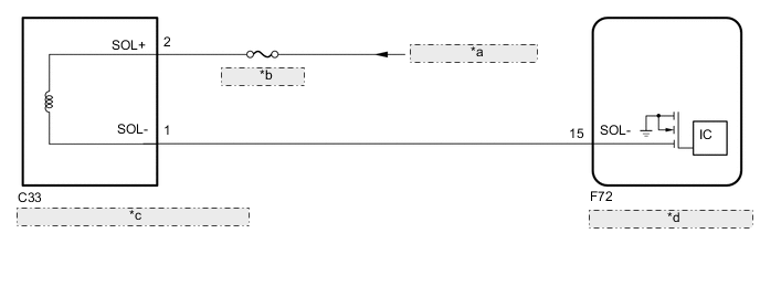
| *a | from IG1-NO. 1 Relay |
| *b | ECU-IG1 NO. 4 |
| *c | Compressor with Pulley Assembly (Compressor Solenoid) |
| *d | Air Conditioning Amplifier Assembly |
CAUTION / NOTICE / HINT
Note
Inspect the fuses for circuits related to this system before performing the following procedure.
PROCEDURE
-
INSPECT COMPRESSOR WITH PULLEY ASSEMBLY (COMPRESSOR SOLENOID)
-
Remove the compressor with pulley assembly (compressor solenoid).
-
Inspect the compressor with pulley assembly (compressor solenoid).
Result Proceed to OK NG
NG 
REPLACE COMPRESSOR WITH PULLEY ASSEMBLY (COMPRESSOR SOLENOID) Click here
OK 
-
-
CHECK HARNESS AND CONNECTOR (COMPRESSOR WITH PULLEY ASSEMBLY (COMPRESSOR SOLENOID) - POWER SOURCE)
-
Measure the resistance according to the value(s) in the table below.
Standard Resistance Tester Connection Switch Condition Specified Condition C33-2 (SOL+) - Body ground Ignition switch ON 11 to 14 V Result Proceed to OK NG
NG
REPAIR OR REPLACE HARNESS OR CONNECTOR
OK
-
-
CHECK HARNESS AND CONNECTOR (COMPRESSOR WITH PULLEY ASSEMBLY (COMPRESSOR SOLENOID) - AIR CONDITIONING AMPLIFIER ASSEMBLY)
-
Disconnect the F72 air conditioning amplifier assembly connector.
-
Measure the resistance according to the value(s) in the table below.
Standard Resistance Tester Connection Condition Specified Condition C33-1 (SOL-) - F72-15 (SOL-) Always Below 1 Ω C33-1 (SOL-) or F72-15 (SOL-) - Body ground Always 10 kΩ or higher Result Result Proceed to NG A OK (When troubleshooting according to the Problem Symptoms Table) B OK (When troubleshooting according to the DTC) C
A
REPAIR OR REPLACE HARNESS OR CONNECTOR
B
PROCEED TO NEXT SUSPECTED AREA SHOWN IN PROBLEM SYMPTOMS TABLE Click here
C
-
-
CHECK FOR DTC
-
Clear the DTCs.
Body Electrical > Air Conditioner > Clear DTCs -
Check for DTCs.
Body Electrical > Air Conditioner > Trouble CodesResult Result Proceed to DTCs are not output A DTCs are output B
A
USE SIMULATION METHOD TO CHECK Click here
B
REPLACE AIR CONDITIONING AMPLIFIER ASSEMBLY Click here
-