AIR CONDITIONING SYSTEM(for Automatic Air Conditioning System with Top-mounted Air Conditioner Pressure Sensor), Diagnostic DTC:B1454
| DTC Code | DTC Name |
|---|---|
| B1454 | Air Outlet Damper Cool Control Servo Motor Circuit (Passenger Side) |
DESCRIPTION
According to signals from the air conditioning amplifier assembly that are based on user operation or air conditioning system control, the No. 1 air conditioning radiator damper servo sub-assembly (front passenger side lower air mix) actuates the servo motor.
The cold air that has passed through the evaporator and the warm air that has passed through the heater core are regulated to provide output air at the selected temperature.
| DTC No. | Detection Item | DTC Detection Condition | Trouble Area | Memory |
|---|---|---|---|---|
| B1454 | Air Outlet Damper Cool Control Servo Motor Circuit (Passenger Side) | Any of the following conditions is met:
|
|
Memorized (30 seconds or more) |
Tech Tips
The air conditioning amplifier assembly stores this DTC if the malfunction has occurred for the period of time indicated in the brackets.
| Vehicle Condition | |||
|---|---|---|---|
| Pattern 1 | Pattern 2 | ||
| Diagnosis Condition | Ignition switch ON | ○ | ○ |
| Malfunction Status | No. 1 air conditioning radiator damper servo sub-assembly (front passenger side lower air mix) drive terminal is open circuit | ○ | - |
| No. 1 air conditioning radiator damper servo sub-assembly (front passenger side lower air mix) drive terminal is short circuit | - | ○ | |
| Detection Time | 30 seconds or more | 30 seconds or more | |
| Number of Trips | 1 trip | 1 trip | |
Tech Tips
DTC will be output when conditions for either of the patterns in the table above are met.
WIRING DIAGRAM
-
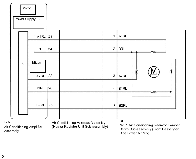
for LHD
-
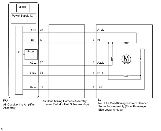
for RHD
CAUTION / NOTICE / HINT
PROCEDURE
-
PERFORM ACTIVE TEST USING GTS (LOWER AIR MIX (PASSENGER SIDE))
-
Connect the GTS to the DLC3.
-
Turn the ignition switch ON.
-
Turn the GTS on.
-
Enter the following menus: Body Electrical / Air Conditioner / Active Test.
-
Perform the Active Test according to the display on the GTS.
Body Electrical > Air Conditioner > Active TestTester Display Measurement Item Control Range Diagnostic Note Lower Air Mix (Passenger Side) No. 1 air conditioning radiator damper servo sub-assembly (front passenger side lower air mix) Min.: 0
Max.: 100
Operates between
0 to 100%
Body Electrical > Air Conditioner > Active TestTester Display Lower Air Mix (Passenger Side) OK No. 1 air conditioning radiator damper servo sub-assembly (front passenger side lower air mix) operates normally. Result Result Proceed to NG (When troubleshooting according to Problem Symptoms Table) A OK (When troubleshooting according to the DTC) B NG (When troubleshooting according to Problem Symptoms Table) C OK (When troubleshooting according to the DTC) D
B 
INSPECT AIR CONDITIONING HARNESS ASSEMBLY (HEATER RADIATOR UNIT SUB-ASSEMBLY) Click here
C 
PROCEED TO NEXT SUSPECTED AREA SHOWN IN PROBLEM SYMPTOMS TABLE Click here
D
CHECK FOR DTC Click here
A 
-
-
INSPECT NO. 1 AIR CONDITIONING RADIATOR DAMPER SERVO SUB-ASSEMBLY (FRONT PASSENGER SIDE LOWER AIR MIX) (MOTOR, LINK, DAMPER)
-
Check for a wire harness caught between the links of the motors and dampers.
OK No wire harnesses are caught between the links of the motors and dampers. Result Proceed to OK NG
NG
REMOVE PINCHED WIRE HARNESS
OK
-
-
INSPECT AIR CONDITIONING RADIATOR ASSEMBLY (DAMPER)
-
Remove the No. 1 air conditioning radiator damper servo sub-assembly (front passenger side lower air mix).
-
Operate the dampers by hand.
OK The dampers are easily operated by hand. Result Proceed to OK NG
NG
REPLACE No. 1 AIR CONDITIONING RADIATOR DAMPER SERVO SUB-ASSEMBLY (FRONT PASSENGER SIDE LOWER AIR MIX) Click here
OK
-
-
INSPECT AIR CONDITIONING HARNESS ASSEMBLY (HEATER RADIATOR UNIT SUB-ASSEMBLY)
-
Remove the air conditioning harness assembly (heater radiator unit sub-assembly).
-
for LHD
-
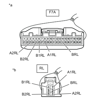
*a Front view of wire harness connector
(to Air Conditioning Amplifier Assembly)
*b Front view of wire harness connector
(to No. 1 Air Conditioning Radiator Damper Servo Sub-assembly (Front Passenger Side Lower Air Mix))
Measure the resistance according to the value(s) inthe table below.
Standard Resistance Tester Connection Condition Specified Condition F7A-28 (A1RL) - RL-1 (A1RL) Always Below 1 Ω F7A-34 (BRL) - RL-2 (BRL) Always Below 1 Ω F7A-23 (A2RL) - RL-3 (A2RL) Always Below 1 Ω F7A-26 (B1RL) - RL-4 (B1RL) Always Below 1 Ω F7A-25 (B2RL) - RL-6 (B2RL) Always Below 1 Ω F7A-28 (A1RL) or RL-1 (A1RL) - Body ground Always 10 kΩ or higher F7A-34 (BRL) or RL-2 (BRL) - Body ground Always 10 kΩ or higher F7A-23 (A2RL) or RL-3 (A2RL) - Body ground Always 10 kΩ or higher F7A-26 (B1RL) or RL-4 (B1RL) - Body ground Always 10 kΩ or higher F7A-25 (B2RL) or RL-6 (B2RL) - Body ground Always 10 kΩ or higher
-
-
for RHD
-
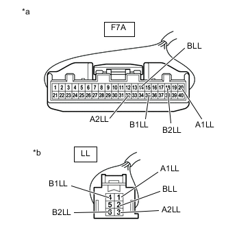
*a Front view of wire harness connector
(to Air Conditioning Amplifier Assembly)
*b Front view of wire harness connector
(to No. 1 Air Conditioning Radiator Damper Servo Sub-assembly (Front Passenger Side Lower Air Mix))
Measure the resistance according to the value(s) in the table below.
Standard Resistance Tester Connection Condition Specified Condition F7A-20 (A1LL) - LL-1 (A1LL) Always Below 1 Ω F7A-14 (BLL) - LL-2 (BLL) Always Below 1 Ω F7A-32 (A2LL) - LL-3 (A2LL) Always Below 1 Ω F7A-35 (B1LL) - LL-4 (B1LL) Always Below 1 Ω F7A-18 (B2LL) - LL-6 (B2LL) Always Below 1 Ω F7A-20 (A1LL) or LL-1 (A1LL) - Body ground Always 10 kΩ or higher F7A-14 (BLL) or LL-2 (BLL) - Body ground Always 10 kΩ or higher F7A-37 (A2LL) or LL-3 (A2LL) - Body ground Always 10 kΩ or higher F7A-35 (B1LL) or LL-4 (B1LL) - Body ground Always 10 kΩ or higher F7A-18 (B2LL) or LL-6 (B2LL) - Body ground Always 10 kΩ or higher
Result Proceed to OK NG -
NG
REPLACE AIR CONDITIONING HARNESS ASSEMBLY (HEATER RADIATOR UNIT SUB-ASSEMBLY Click here
OK
-
-
REPLACE NO. 1 AIR CONDITIONING RADIATOR DAMPER SERVO SUB-ASSEMBLY (FRONT PASSENGER SIDE LOWER AIR MIX)
-
Replace the No. 1 air conditioning radiator damper servo sub-assembly (front passenger side lower air mix) with a new one or the No. 1 air conditioning radiator damper servo sub-assembly (front passenger side upper air mix) if it is functioning properly.
Result Proceed to NEXT
NEXT
-
-
PERFORM ACTIVE TEST USING GTS (UPPER AIR MIX (PASSENGER SIDE))
-
Connect the GTS to the DLC3.
-
Turn the ignition switch ON.
-
Turn the GTS on.
-
Enter the following menus: Body Electrical / Air Conditioner / Active Test.
-
Perform the Active Test according to the display on the GTS.
Body Electrical > Air Conditioner > Active TestTester Display Measurement Item Control Range Diagnostic Note Lower Air Mix (Passenger Side) No. 1 air conditioning radiator damper servo sub-assembly (front passenger side lower air mix) Min.: 0
Max.: 100
Operates between
0 to 100%
Body Electrical > Air Conditioner > Active TestTester Display Lower Air Mix (Passenger Side) OK No. 1 air conditioning radiator damper servo sub-assembly (front passenger side lower air mix) operates normally. Result Proceed to OK NG
OK
REPLACE NO. 1 AIR CONDITIONING RADIATOR DAMPER SERVO SUB-ASSEMBLY (FRONT PASSENGER SIDE LOWER AIR MIX) Click here
NG
-
-
CHECK FOR DTC
-
Clear the DTCs.
Body Electrical > Air Conditioner > Clear DTCs -
Check for DTCs.
Body Electrical > Air Conditioner > Trouble CodesResult Result Proceed to DTCs are not output A DTCs are output B
A
USE SIMULATION METHOD TO CHECK Click here
B
REPLACE AIR CONDITIONING AMPLIFIER ASSEMBLY Click here
-