AIR CONDITIONING SYSTEM(for Automatic Air Conditioning System with Side-mounted Air Conditioner Pressure Sensor), Diagnostic DTC:B1442
| DTC Code | DTC Name |
|---|---|
| B1442 | Air Inlet Damper Control Servo Motor Circuit |
DESCRIPTION
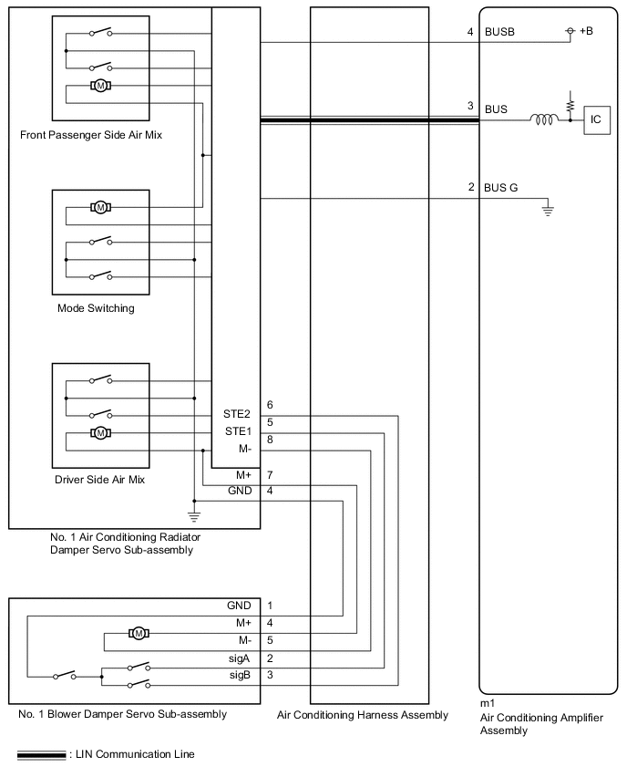
The No. 1 blower damper servo sub-assembly sends pulse signals to inform the air conditioning amplifier assembly of the damper position. The air conditioning amplifier assembly activates the motor (normal or reverse) based on these signals to move the air inlet damper to the appropriate position to change the air inlet mode (fresh, recirculation/fresh, and recirculation).
The air conditioning amplifier assembly communicates with the servo through a communication/driver IC and wiring assembly called the air conditioning harness assembly.
| DTC No. | Detection Item | DTC Detection Condition | Trouble Area | Memory |
|---|---|---|---|---|
| B1442 | Air Inlet Damper Control Servo Motor Circuit | Air inlet damper position sensor value does not change even if air conditioning amplifier assembly operates No. 1 blower damper servo sub-assembly |
|
Memorized (30 seconds or more)* |
-
*: The air conditioning amplifier assembly stores this DTC if the malfunction has occurred for the period of time indicated in the brackets.
WIRING DIAGRAM
CAUTION / NOTICE / HINT
Tech Tips
-
Confirm that no mechanical problem is present because this DTC can be output when either a damper link or damper is mechanically locked.
-
When installing the damper servo motor, make sure to install it correctly.
PROCEDURE
-
CHECK FOR DTC
-
Check for DTCs.
Body Electrical > Air Conditioner > Trouble CodesResult Result Proceed to DTC B1497 is output A DTC B1441, B1442, B1443 and B1446 are output B DTC B1442 is output C
A 
GO TO DTC B1497 Click here
B
REPLACE NO. 1 AIR CONDITIONING RADIATOR DAMPER SERVO SUB-ASSEMBLY Click here
C 
-
-
INSPECT BLOWER ASSEMBLY
-
Remove the No. 1 blower damper servo sub-assembly.
-
Operate the air inlet control dampers by hand.
OK The air inlet control dampers are easily operated by hand. Result Proceed to OK NG
NG
REPLACE BLOWER ASSEMBLY Click here
OK
-
-
INSPECT AIR CONDITIONING HARNESS ASSEMBLY
-
Disconnect the No. 1 air conditioning radiator damper servo sub-assembly connector.
-
Disconnect the No. 1 blower damper servo sub-assembly connector.
-
Measure the resistance according to the value(s) in the table below.
Standard Resistance Tester Connection Condition Specified Condition 6 (STE2) - 3 (sigB) Always Below 1 Ω 5 (STE1) - 2 (sigA) Always Below 1 Ω 8 (M-) - 5 (M-) Always Below 1 Ω 7 (M+) - 4 (M+) Always Below 1 Ω 4 (GND) - 1 (GND) Always Below 1 Ω 6 (STE2) or 3 (sigB) - Body ground Always 10 kΩ or higher 5 (STE1) or 2 (sigA) - Body ground Always 10 kΩ or higher 8 (M-) or 5 (M-) - Body ground Always 10 kΩ or higher 7 (M+) or 4 (M+) - Body ground Always 10 kΩ or higher Result Proceed to OK NG
NG
REPLACE AIR CONDITIONING HARNESS ASSEMBLY Click here
OK
-
-
PERFORM ACTIVE TEST USING GTS (AIR INLET DAMPER TARG PULSE)
-
Reconnect the No. 1 air conditioning radiator damper servo sub-assembly connector.
-
Reconnect the No. 1 blower damper servo sub-assembly connector.
-
Connect the GTS to the DLC3.
-
Turn the ignition switch to ON.
-
Turn the GTS on.
-
Enter the following menus: Body Electrical / Air Conditioner / Active test.
-
Perform the Active Test according to the display on the GTS.
Body Electrical > Air Conditioner > Active TestTester Display Measurement Item Control Range Diagnostic Note Air Inlet Damper Targ Pulse No. 1 blower damper servo sub-assembly pulse Min.: 128
Max.: 383
Operates between 220 to 256 pulses
Body Electrical > Air Conditioner > Active TestTester Display Air Inlet Damper Targ Pulse OK No. 1 blower damper servo sub-assembly pulse operates smoothly. Result Result Proceed to No. 1 blower damper servo sub-assembly pulse are malfunctioning A No. 1 blower damper servo sub-assembly pulse is normal B
B 
INSPECT NO. 1 AIR CONDITIONING RADIATOR DAMPER SERVO SUB-ASSEMBLY Click here
A
-
-
CHECK HARNESS AND CONNECTOR (NO. 1 BLOWER DAMPER SERVO SUB-ASSEMBLY - BODY GROUND)
-
Disconnect the No. 1 blower damper servo sub-assembly connector.
-
Measure the resistance according to the value(s) in the table below.
Standard Resistance Tester Connection Condition Specified Condition 1 (GND) - Body ground Always Below 1 Ω Result Proceed to OK NG
NG
REPLACE NO. 1 AIR CONDITIONING RADIATOR DAMPER SERVO SUB-ASSEMBLY Click here
OK
-
-
INSPECT NO. 1 AIR CONDITIONING RADIATOR DAMPER SERVO SUB-ASSEMBLY
-
Measure the voltage according to the value(s) in the table below.
Tester Connection Condition Specified Condition 4 (M+) - Body ground
-
Ignition switch ON
-
No. 1 blower damper servo sub-assembly operating (fresh)
11 to 14 V ←→ Below 1 V 5 (M-) - Body ground
-
Ignition switch ON
-
No. 1 blower damper servo sub-assembly operating (recirculation)
11 to 14 V ←→ Below 1 V Result Proceed to OK NG -
OK
REPLACE NO. 1 BLOWER DAMPER SERVO SUB-ASSEMBLY Click here
NG
REPLACE NO. 1 AIR CONDITIONING RADIATOR DAMPER SERVO SUB-ASSEMBLY Click here
-
-
INSPECT NO. 1 AIR CONDITIONING RADIATOR DAMPER SERVO SUB-ASSEMBLY
-
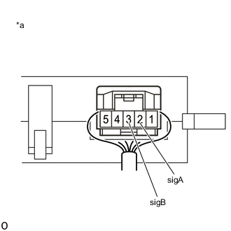
*a Component with harness connected
(No. 1 Blower Damper Servo Sub-assembly)
Measure the voltage according to the value(s) in the table below.
Standard Voltage Tester Connection Switch Condition Specified Condition 2 (sigA) - Body ground Ignition switch ON 4.75 V to 5.25 V 3 (sigB) - Body ground Ignition switch ON 4.75 V to 5.25 V Result Proceed to OK NG
NG
REPLACE NO. 1 AIR CONDITIONING RADIATOR DAMPER SERVO SUB-ASSEMBLY Click here
OK
-
-
INSPECT NO. 1 BLOWER DAMPER SERVO SUB-ASSEMBLY
-
Turn the ignition switch ON.
-
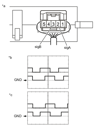
*a Component with harness connected
(No. 1 blower damper servo sub-assembly)
*b Fresh wave form *c Recirculation wave form Connect an oscilloscope to terminals 2 (sig A) and 3 (sig B) of the air conditioning amplifier assembly and check the waveform.
OK Waveform is similar to that shown in the illustration. Item Content Tool Setting 2.5 V/DIV., 200 ms./DIV. Vehicle Condition
-
Ignition switch ON
-
No. 1 blower damper servo sub-assembly operating
Result Proceed to OK NG -
OK
REPLACE NO. 1 AIR CONDITIONING RADIATOR DAMPER SERVO SUB-ASSEMBLY Click here
NG
REPLACE NO. 1 BLOWER DAMPER SERVO SUB-ASSEMBLY Click here
-