FRONT SEAT OUTER BELT ASSEMBLY INSTALLATION

Info Added 2017-10-06 ![]()
CAUTION / NOTICE / HINT
Tech Tips
-
Use the same procedure for RHD and LHD vehicles.
-
The procedure listed below is for LHD vehicles.
-
Use the same procedure for the RH side and LH side.
-
The procedure listed below is for the LH side.
PROCEDURE
-
INSTALL FRONT SHOULDER BELT ANCHOR ADJUSTER ASSEMBLY
-
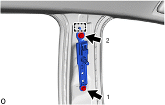
Engage the guide and temporarily install the front shoulder belt anchor adjuster assembly with the 2 bolts.
-
Tighten the 2 bolts in the order shown in the illustration.
- Torque:
- 42 N*m { 428 kgf*cm, 31 ft.*lbf }
-
-
INSPECT FRONT SEAT OUTER BELT ASSEMBLY
-
INSTALL FRONT SEAT OUTER BELT ASSEMBLY
-
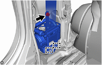
Engage the guides to install the front seat outer belt assembly.
-
Install the bolt.
- Torque:
- 12.5 N*m { 127 kgf*cm, 9 ft.*lbf }
-
for TMMT Made:
-
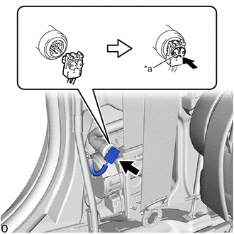
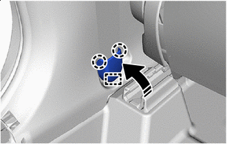
*a Locking Button Connect the pretensioner connector and lock the locking button as shown in the illustration.
Note
Securely lock the locking button.
-
-
except TMMT Made:
-
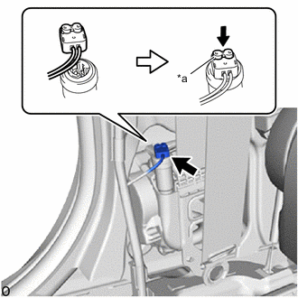
*a Locking Button Connect the pretensioner connector and lock the locking button as shown in the illustration.
Note
Securely lock the locking button.
-
-
Connect the shoulder anchor of the front seat outer belt assembly with the nut.
- Torque:
- 42 N*m { 428 kgf*cm, 31 ft.*lbf }
-
Install the bolt of retractor lower side.
- Torque:
- 42 N*m { 428 kgf*cm, 31 ft.*lbf }
-
Check that the ELR locks.
Note
This check should be performed with the front seat outer belt assembly installed to the vehicle.
-
With the front seat outer belt assembly installed to the vehicle, check that the belt locks when it is pulled out quickly.
-
-
Remove the bolt of retractor lower side.
-
-
INSTALL CENTER PILLAR GARNISH ASSEMBLY
-
INSTALL CENTER PILLAR LOWER GARNISH
-
CONNECT FRONT SEAT OUTER BELT ASSEMBLY
-
Connect the floor anchor of the front seat outer belt assembly with the bolt.
- Torque:
- 42 N*m { 428 kgf*cm, 31 ft.*lbf }
-
-
INSTALL LAP BELT OUTER ANCHOR COVER
-

Install in this Direction Engage the guide and claws to install the lap belt outer anchor cover.
-
-
CONNECT REAR DOOR OPENING TRIM WEATHERSTRIP
-
Connect the rear door opening trim weatherstrip.
-
-
INSTALL REAR DOOR SCUFF PLATE
-
CONNECT FRONT DOOR OPENING TRIM WEATHERSTRIP
-
Connect the front door opening trim weatherstrip.
-
-
INSTALL FRONT DOOR SCUFF PLATE
-
CONNECT CABLE TO NEGATIVE BATTERY TERMINAL
-
for 8NR-FTS:
-
for 3ZR-FAE:
Note
When disconnecting the cable, some systems need to be initialized after the cable is reconnected.
-
-
PERFORM DIAGNOSTIC SYSTEM CHECK
-
INSPECT SRS WARNING LIGHT