SIDE AIRBAG SENSOR(for Center Pillar) REMOVAL
Info Added 2017-10-06 ![]()
CAUTION / NOTICE / HINT
The necessary procedures (adjustment, calibration, initialization, or registration) that must be performed after parts are removed, installed, or replaced during the side airbag sensor removal/installation are shown below.
| Replacement Part or Procedure | Necessary Procedures | Effects/Inoperative when not performed | Link |
|---|---|---|---|
| Disconnect cable from negative battery terminal | Memorize steering angle neutral point | Lane departure alert system (w/ Steering Control) | |
| Simple intelligent parking assist system*1 | |||
| Toyota parking assist-sensor system (w/ Simple Intelligent Parking Assist System)*1 | |||
| Pre-collision system | |||
| Initialize back door lock | Power door lock control system | ||
| Drive the vehicle until stop and start control is permitted (approximately 5 to 60 minutes)*2 | Stop and start system |
*1: When performing learning using the GTS.
*2: w/ Stop and start system
Tech Tips
-
Use the same procedure for RHD and LHD vehicles.
-
The following procedure is for LHD vehicles.
-
Use the same procedure for the RH side and LH side.
-
The following procedure is for the LH side.
PROCEDURE
-
PRECAUTION
Note
After turning the ignition switch off, waiting time may be required before disconnecting the cable from the negative (-) battery terminal. Therefore, make sure to read the disconnecting the cable from the negative (-) battery terminal notices before proceeding with work.
-
DISCONNECT CABLE FROM NEGATIVE BATTERY TERMINAL
-
for 8NR-FTS:
-
for 3ZR-FAE:
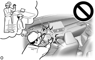
CAUTION:
-
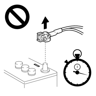
Wait at least 90 seconds after disconnecting the cable from the negative (-) battery terminal to disable the SRS system.
-
If an SRS part is accidentally deployed, it may cause a serious injury.
Note
When disconnecting the cable, some systems need to be initialized after the cable is reconnected.
-
-
REMOVE LAP BELT OUTER ANCHOR COVER
-
DISCONNECT FRONT SEAT OUTER BELT ASSEMBLY
-
REMOVE FRONT DOOR SCUFF PLATE
-
DISCONNECT FRONT DOOR OPENING TRIM WEATHERSTRIP
Tech Tips
Disconnect the front door opening trim weatherstrip to the extent that allows the removal of the center pillar lower garnish.
-
REMOVE REAR DOOR SCUFF PLATE
-
DISCONNECT REAR DOOR OPENING TRIM WEATHERSTRIP
Tech Tips
Disconnect the rear door opening trim weatherstrip to the extent that allows the removal of the center pillar lower garnish.
-
REMOVE CENTER PILLAR LOWER GARNISH
-
REMOVE NO. 1 SIDE AIRBAG SENSOR
-
Check that the ignition switch off.
-
Check that the cable is disconnected from the negative (-) battery terminal.
CAUTION:
Wait at least 90 seconds after disconnecting the cable from the negative (-) battery terminal to disable the SRS system.
-
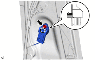
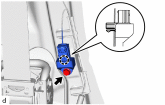
Remove the bolt and disengage the claw to separate the No. 1 side airbag sensor.
-
Disconnect the connector to remove the No. 1 side airbag sensor.
Note
When disconnecting any airbag connector, take care not to damage the airbag wire harness.
-
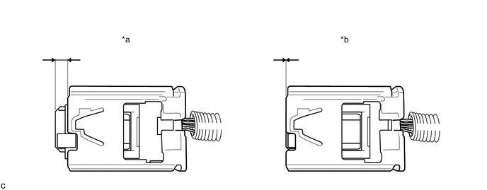
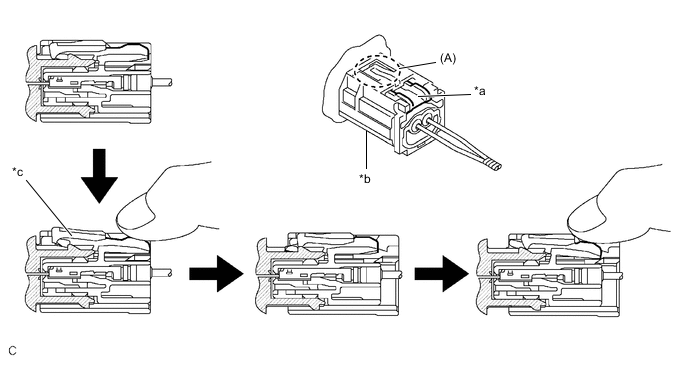
Push down the white housing lock and slide the yellow CPA. (At this time, the connector cannot be disconnected yet.)
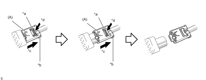
*a White Housing Lock *b Yellow CPA *c Slide *d Push -
Push down the white housing lock again and disconnect the connector.
Note
Do not push down the part (A) shown in the illustration when disconnecting the connector.
-
-
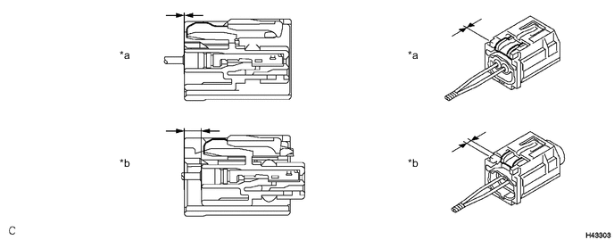
After disconnecting the connector, check that the position of the white housing lock is as shown in the illustration.
*a Correct *b Incorrect
-
-
REMOVE FLOOR SIDE AIRBAG SENSOR
-
Check that the ignition switch off.
-
Check that the cable is disconnected from the negative (-) battery terminal.
CAUTION:
Wait at least 90 seconds after disconnecting the cable from the negative (-) battery terminal to disable the SRS system.
-
Remove the bolt and disengage the claw to separate the floor side airbag sensor.
-
Disconnect the connector to remove the floor side airbag sensor.
Note
When disconnecting any airbag connector, take care not to damage the airbag wire harness.
-
Push down the white housing lock and slide the yellow CPA. (At this time, the connector cannot be disconnected yet.)
*a White Housing Lock *b Yellow CPA *c Connector lock is released - - -
Push down the white housing lock again and disconnect the connector.
Note
Do not push down the part (A) shown in the illustration when disconnecting the connector.
-
-
Check that the position of the white housing lock is as shown in the illustration.
*a Incorrect *b Correct
-