SPIRAL CABLE REMOVAL
Info Added 2017-10-06 ![]()
CAUTION / NOTICE / HINT
The necessary procedures (adjustment, calibration, initialization, or registration) that must be performed after parts are removed, installed, or replaced during the spiral cable sub-assembly removal/installation are shown below.
| Replacement Part or Procedure | Necessary Procedures | Effect/Inoperative when not Performed | Link |
|---|---|---|---|
| Disconnect cable from negative battery terminal | Memorize steering angle neutral point | Lane departure alert system (w/ Steering Control) | |
| Simple intelligent parking assist system*1 | |||
| Toyota parking assist-sensor system (w/ Simple Intelligent Parking Assist System)*1 | |||
| Pre-collision system | |||
| Initialize back door lock | Power door lock control system | ||
| Drive the vehicle until stop and start control is permitted (approximately 5 to 60 minutes)*2 | Stop and start system | ||
| Removal/installation of the spiral cable with sensor sub-assembly | Steering angle neutral point (Initialize panoramic view monitor system) |
|
*1: When performing learning using the GTS.
*2: w/ Stop and start system
Tech Tips
-
Use the same procedure for RHD and LHD vehicles.
-
The following procedure is for LHD vehicles.
PROCEDURE
-
REMOVE STEERING WHEEL ASSEMBLY
-
ALIGN FRONT WHEELS FACING STRAIGHT AHEAD
-
INSPECT SPIRAL CABLE WITH SENSOR SUB-ASSEMBLY (w/o Steering Heater)
-
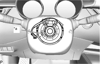
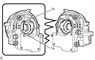
*a Flat Cable Check the flat cable shown in the illustration.
If the flat cable shown in the illustration is not visible, it is possible that the spiral cable with sensor sub-assembly is broken. Replace the spiral cable with sensor sub-assembly with a new one.
-
-
INSPECT SPIRAL CABLE WITH SENSOR SUB-ASSEMBLY (w/ Steering Heater)
-
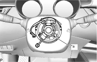
*a Flat Cable Check the flat cable shown in the illustration.
If the flat cable shown in the illustration is not visible, it is possible that the spiral cable with sensor sub-assembly is broken. Replace the spiral cable with sensor sub-assembly with a new one.
-
-
REMOVE LOWER STEERING COLUMN COVER
-
REMOVE UPPER STEERING COLUMN COVER
-
REMOVE SPIRAL CABLE WITH SENSOR SUB-ASSEMBLY
Note
-
Do not replace the spiral cable with sensor sub-assembly with the battery connected and the ignition switch ON.
-
Do not rotate the spiral cable with sensor sub-assembly without the steering wheel assembly installed, with the battery connected and the ignition switch ON.
-
Ensure that the steering wheel assembly is installed and aligned straight when inspecting the steering sensor.
-
Check that the ignition switch off.
-
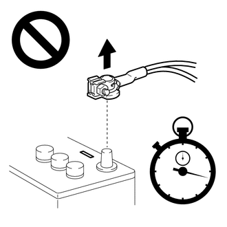
Check that the cable is disconnected from the negative (-) battery terminal.
CAUTION:
Wait at least 90 seconds after disconnecting the cable from the negative (-) battery terminal to disable the SRS system.
-
Check that the front wheels are aligned facing straight ahead.
-
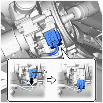
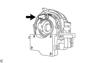
*a Slider Slide the slider to release the lock, and then disconnect the yellow airbag connector from the spiral cable with sensor sub-assembly.
Note
When disconnecting any airbag connector, take care not to damage the airbag wire harness.
-
Disconnect each connector from the spiral cable with sensor sub-assembly.
-
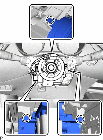
Disengage the claws to remove the spiral cable with sensor sub-assembly.
-
-
REMOVE SPIRAL CABLE SUB-ASSEMBLY
Note
-
Remove the steering sensor from the spiral cable sub-assembly only when replacing the spiral cable sub-assembly.
-
Removing the steering sensor from the spiral cable sub-assembly without using a lock pin may result in the center position of the steering sensor becoming misaligned. Therefore, make sure to use the lock pin provided with a new spiral cable sub-assembly when removing the steering sensor from the spiral cable sub-assembly.
-
When replacing the steering sensor:
-
Install the lock pin to the steering sensor.
Note
-
Use the lock pin provided with a new spiral cable sub-assembly.
-
Do not remove the lock pin before installing the steering sensor to the spiral cable sub-assembly.
-
-
*a Guide Disengage the claws and pins, and remove the spiral cable sub-assembly from the steering sensor.
Note
Do not damage the pins of the spiral cable sub-assembly or guides of the steering sensor.
-
-