STEERING PAD REMOVAL

Info Added 2017-10-06 ![]()
CAUTION / NOTICE / HINT
The necessary procedures (adjustment, calibration, initialization, or registration) that must be performed after parts are removed, installed, or replaced during the horn button assembly removal/installation are shown below.
| Replacement Part or Procedure | Necessary Procedures | Effects/Inoperative when not performed | Link |
|---|---|---|---|
| Disconnect cable from negative battery terminal | Memorize steering angle neutral point | Lane departure alert system (w/ Steering Control) | |
| Simple intelligent parking assist system*1 | |||
| Toyota parking assist-sensor system (w/ Simple Intelligent Parking Assist System)*1 | |||
| Pre-collision system | |||
| Initialize back door lock | Power door lock control system | ||
| Drive the vehicle until stop and start control is permitted (approximately 5 to 60 minutes)*2 | Stop and start system |
*1: When performing learning using the GTS.
*2: w/ Stop and start system
Tech Tips
-
Use the same procedure for RHD and LHD vehicles.
-
The following procedure is for LHD vehicles.
PROCEDURE
-
PRECAUTION
Note
After turning the ignition switch off, waiting time may be required before disconnecting the cable from the negative (-) battery terminal. Therefore, make sure to read the disconnecting the cable from the negative (-) battery terminal notices before proceeding with work.
-
DISCONNECT CABLE FROM NEGATIVE BATTERY TERMINAL
-
for 8NR-FTS:
-
for 3ZR-FAE:
CAUTION:
-
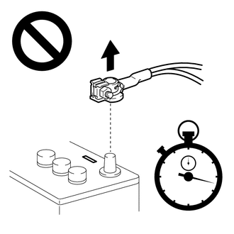
Wait at least 90 seconds after disconnecting the cable from the negative (-) battery terminal to disable the SRS system.
-
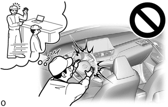
If an SRS part is accidentally deployed, it may cause a serious injury.
Note
When disconnecting the cable, some systems need to be initialized after the cable is reconnected.
-
-
REMOVE HORN BUTTON ASSEMBLY
CAUTION:
When storing the horn button assembly, keep the airbag deployment side facing upward.
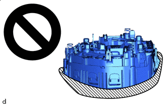

Deployment Side
-
Check that the ignition switch off.
-
Check that the cable is disconnected from the negative (-) battery terminal.
CAUTION:
Wait at least 90 seconds after disconnecting the cable from the negative (-) battery terminal to disable the SRS system.
-
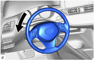
Turn the steering wheel assembly 90° to the left.
-

*a 55 mm (2.17 in.) *b 95 mm (3.74 in.) Protective Tape Wrap protective tape around a 6 mm hexagon wrench as shown in the illustration.
Tech Tips
Use a 6 mm hexagon wrench with a long arm length of approximately 95 mm (3.74 in.).
-
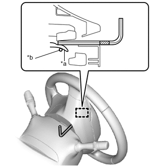
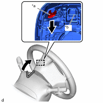
*a Housing Tab *b Omega Spring Protective Tape Insert the 6 mm hexagon wrench into the service hole until the protective tape is at the position shown in the illustration.
Tech Tips
Make sure to insert the 6 mm hexagon wrench into the service hole on the backside of the steering wheel assembly.
-
*a Housing Tab *b Omega Spring Using the 6 mm hexagon wrench, push down the housing tab to disengage the hook as shown in the illustration.
Tech Tips
Pushing down the housing tab will push the omega spring and disengage it from the hook.
-
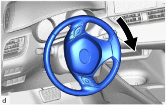
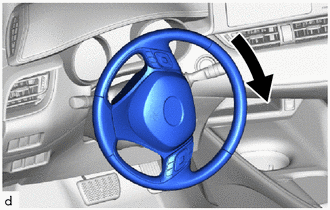
Turn the steering wheel assembly 180° to the right.
-
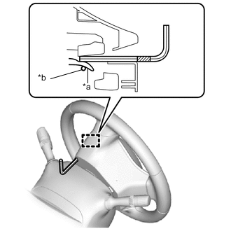
*a Housing Tab *b Omega Spring Protective Tape Insert the 6 mm hexagon wrench into the service hole until the protective tape is at the position shown in the illustration.
Tech Tips
Make sure to insert the 6 mm hexagon wrench into the service hole on the backside of the steering wheel assembly.
-
*a Housing Tab *b Omega Spring Using the 6 mm hexagon wrench, push down the housing tab to disengage the hook as shown in the illustration.
Note
Lightly hold the horn button assembly so that it does not fall.
Tech Tips
Pushing down the housing tab will push the omega spring and disengage it from the hook.
-
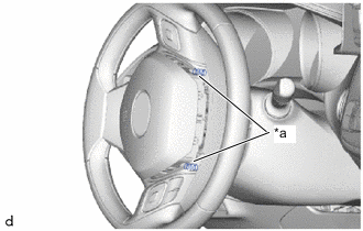
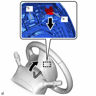
*a Spring Check that each hook is disengaged.
Tech Tips
If a hook is disengaged, the spring will be visible at the location shown in the illustration.
-
Turn the steering wheel assembly 90° to the right.
-
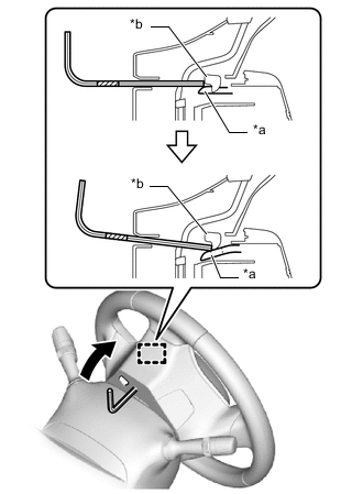
*a Housing Tab *b Hook Using a 6 mm hexagon wrench, push the housing tab to disengage the hook as shown in the illustration.
Note
Lightly hold the horn button assembly so that it does not fall.
Tech Tips
-
Insert the 6 mm hexagon wrench into the service hole until it contacts the hook and then push down the housing tab while pushing it toward the rear of the vehicle.
-
Pushing down the housing tab will disengage it from the hook.
-
-
Turn the steering wheel assembly 180° to the left to align the front wheels facing straight ahead.
Note
Do not drop the horn button assembly.
-
Pull out the horn button assembly from the steering wheel assembly and hold the horn button assembly with one hand.
Note
When separating the horn button assembly, do not pull the airbag wire harness.
-
for Single Type:
-
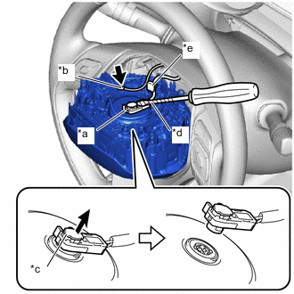
*a Airbag Connector *b Horn Connector *c Airbag Connector Lock *d Protective Tape *e Wire Harness Clamp Disconnect the horn connector from the horn button assembly.
-
Using a screwdriver with its tip wrapped in protective tape, release the airbag connector lock.
-
Disconnect the airbag connector.
-
Disengage the wire harness clamp to remove the horn button assembly
Note
When disconnecting any airbag connector, take care not to damage the airbag wire harness.
-
-
for Dual Type:
-
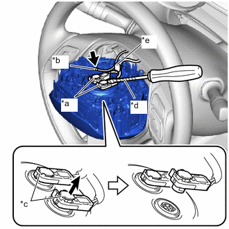
*a Airbag Connector *b Horn Connector *c Airbag Connector Lock *d Protective Tape *e Wire Harness Clamp Disconnect the horn connector from the horn button assembly.
-
Using a screwdriver with its tip wrapped in protective tape, release the 2 airbag connector locks.
-
Disconnect the 2 airbag connectors.
-
Disengage the wire harness clamp to remove the horn button assembly
Note
When disconnecting any airbag connector, take care not to damage the airbag wire harness.
-
-