METER / GAUGE SYSTEM Steering Pad Switch Circuit
DESCRIPTION
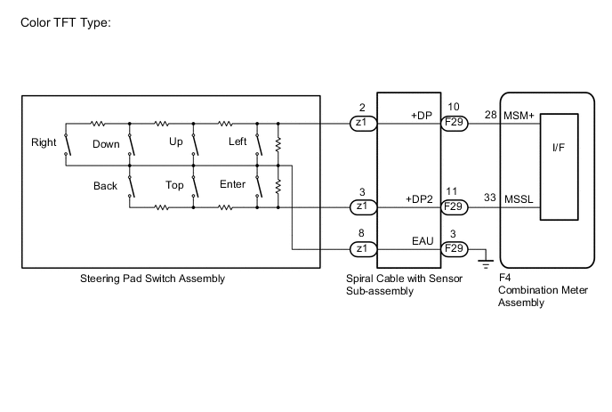
The combination meter assembly and steering pad switch assembly are connected via direct line. The main display and multi-information display in the combination meter assembly are operated using the switches of the steering pad switch assembly.
WIRING DIAGRAM
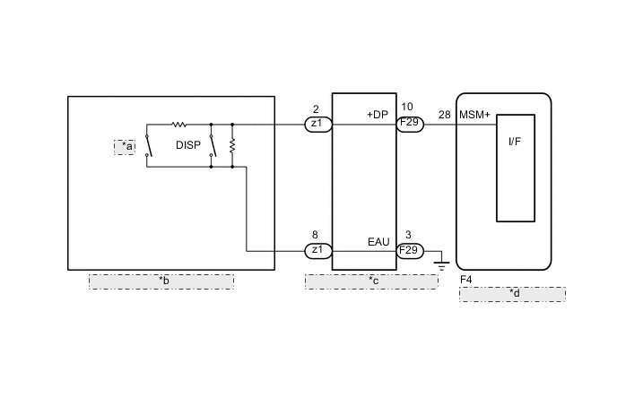
| *a | TRIP |
| *b | Steering Pad Switch Assembly |
| *c | Spiral Cable with Sensor Sub-assembly |
| *d | Combination Meter Assembly |
CAUTION / NOTICE / HINT
Note
When replacing the combination meter assembly, always replace it with a new one. If a combination meter assembly which was installed to another vehicle is used, the information stored in it will not match the information from the vehicle and a DTC may be stored.
PROCEDURE
-
INSPECT STEERING PAD SWITCH ASSEMBLY
-
Remove the steering pad switch assembly.
-
Inspect the steering pad switch assembly.
Result Proceed to OK NG
NG 
REPLACE STEERING PAD SWITCH ASSEMBLY Click here
OK 
-
-
INSPECT SPIRAL CABLE WITH SENSOR SUB-ASSEMBLY
-
Remove the spiral cable with sensor sub-assembly.
-
Inspect the spiral cable with sensor sub-assembly.
Result Proceed to OK NG
NG
REPLACE SPIRAL CABLE WITH SENSOR SUB-ASSEMBLY Click here
OK
-
-
CHECK HARNESS AND CONNECTOR (SPIRAL CABLE WITH SENSOR SUB-ASSEMBLY - COMBINATION METER ASSEMBLY)
-
Disconnect the F4 combination meter assembly connector.
-
Disconnect the F29 spiral cable with sensor sub-assembly connector.
-
Measure the resistance according to the value(s) in the table below.
Standard Resistance Tester Connection Condition Specified Condition F4-28 (MSM+) - F29-10 (+DP) Always Below 1 Ω F4-33 (MSSL) - F29-11 (+DP2)*1 Always Below 1 Ω F29-3 (EAU) - Body ground Always Below 1 Ω F4-28 (MSM+) - Body ground Always 10 kΩ or higher F4-33 (MSSL) - Body ground*1 Always 10 kΩ or higher
-
*1: Color TFT Type
Result Proceed to OK NG -
OK
REPLACE COMBINATION METER ASSEMBLY Click here
NG
REPAIR OR REPLACE HARNESS OR CONNECTOR
-