METER / GAUGE SYSTEM, Diagnostic DTC:B1507, B1508
| DTC Code | DTC Name |
|---|---|
| B1507 | Open in Turn Signal Circuit |
| B1508 | Short in Turn Signal / Hazard Flasher Circuit |
DESCRIPTION
These DTCs are stored when the combination meter assembly detects an open in a turn signal light circuit, or a short in a turn signal light circuit or the hazard warning light circuit.
| DTC No. | Detection Item | DTC Detection Condition | Trouble Area | Memory | Note |
|---|---|---|---|---|---|
| B1507 | Open in Turn Signal Circuit | When IG voltage is 9.5 V or more and the following condition is detected:
|
|
DTC stored | - |
| B1508 | Short in Turn Signal / Hazard Flasher Circuit | When IG voltage is 9.5 V or more and the following condition is detected:
|
|
DTC stored | - |
-
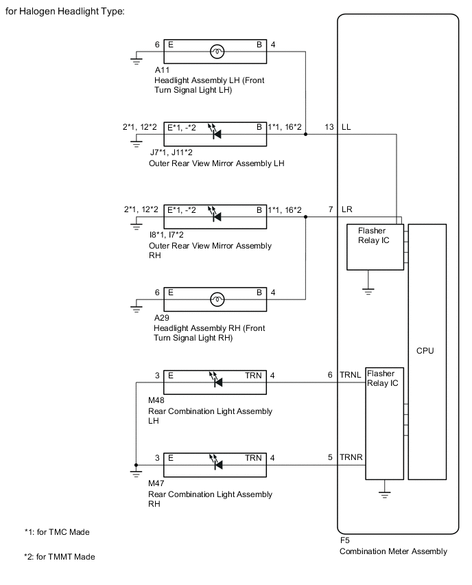
*1: for Halogen Headlight Type
WIRING DIAGRAM
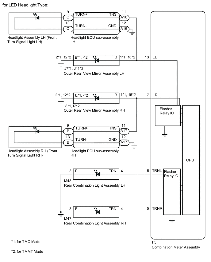
CAUTION / NOTICE / HINT
Note
-
Inspect the LEDs and bulbs for this system before performing the following procedure.
-
When replacing the combination meter assembly, always replace it with a new one. If a combination meter assembly which was installed to another vehicle is used, the information stored in it will not match the information from the vehicle and a DTC may be stored.
PROCEDURE
-
INSPECT LIGHTS
-
Inspect the illumination of each turn signal light.
Result Result Proceed to RH side turn signal light does not illuminate. A LH side turn signal light does not illuminate. B
B 
CHECK TURN SIGNAL LIGHTS (LH SIDE) Click here
A 
-
-
CHECK TURN SIGNAL LIGHTS (RH SIDE)
-
Turn the ignition switch ON.
-
Set the headlight dimmer switch assembly to the right turn switch position.
-
Check the operation of the turn signal lights (RH side).
Result Result Proceed to Front turn signal light assembly (RH side) does not blink. (for LED Headlight Type) A Front turn signal light assembly (RH side) does not blink. (for Halogen Headlight Type) B Side turn signal light assembly (RH side) does not blink. C Rear turn signal light assembly (RH side) does not blink. D
B
CHECK HARNESS AND CONNECTOR (HEADLIGHT ASSEMBLY RH - COMBINATION METER ASSEMBLY OR BODY GROUND) Click here
C
CHECK HARNESS AND CONNECTOR (COMBINATION METER ASSEMBLY - OUTER REAR VIEW MIRROR ASSEMBLY RH) Click here
D
CHECK HARNESS AND CONNECTOR (REAR COMBINATION LIGHT ASSEMBLY RH - COMBINATION METER ASSEMBLY OR BODY GROUND) Click here
A
-
-
CHECK HARNESS AND CONNECTOR (HEADLIGHT ECU SUB-ASSEMBLY RH - COMBINATION METER ASSEMBLY OR BODY GROUND)
-
Disconnect the A17 headlight ECU sub-assembly RH connector.
-
Disconnect the F5 combination meter assembly connector.
-
Measure the resistance according to the value(s) in the table below.
Standard Resistance (Check for Open) Tester Connection Condition Specified Condition A17-11 (TNS) - F5-7 (LR) Always Below 1 Ω A17-12 (GND) - Body ground Always Below 1 Ω Standard Resistance (Check for Short) Tester Connection Condition Specified Condition A17-11 (TNS) - Body ground Always 10 kΩ or higher Result Proceed to OK NG
NG 
REPAIR OR REPLACE HARNESS OR CONNECTOR
OK
-
-
INSPECT HEADLIGHT ECU SUB-ASSEMBLY RH
-
Remove the Headlight ECU sub-assembly RH.
-

*a Component without harness connected
(Headlight ECU sub-assembly RH)
Measure the resistance according to the value(s) in the table below.
Standard Resistance Tester Connection Condition Specified Condition A17-11 (TNS) - B-9 (TURN+) Always Below 1 Ω A17-12 (GND) - B-13 (TURN-) Always Below 1 Ω A17-11 (TNS) - A17-12 (GND) Always 10 kΩ or higher Result Proceed to OK NG
OK
REPLACE COMBINATION METER ASSEMBLY Click here
NG
REPLACE HEADLIGHT ECU SUB-ASSEMBLY RH Click here
-
-
CHECK HARNESS AND CONNECTOR (HEADLIGHT ASSEMBLY RH - COMBINATION METER ASSEMBLY OR BODY GROUND)
-
Disconnect the A29 headlight assembly RH connector.
-
Disconnect the F5 combination meter assembly connector.
-
Measure the resistance according to the value(s) in the table below.
Standard Resistance (Check for Open) Tester Connection Condition Specified Condition A29-4 (B) - F5-7 (LR) Always Below 1 Ω A29-6 (E) - Body ground Always Below 1 Ω Standard Resistance (Check for Short) Tester Connection Condition Specified Condition A29-4 (B) - Body ground Always 10 kΩ or higher Result Proceed to OK NG
OK
REPLACE COMBINATION METER ASSEMBLY Click here
NG
REPAIR OR REPLACE HARNESS OR CONNECTOR
-
-
CHECK HARNESS AND CONNECTOR (COMBINATION METER ASSEMBLY - OUTER REAR VIEW MIRROR ASSEMBLY RH)
-
Disconnect the F5 combination meter assembly connector.
-
Disconnect the I8*1 or I7*2 outer rear view mirror assembly RH connector.
-
Measure the resistance according to the value(s) in the table below.
Standard Resistance (Check for Open) Tester Connection Condition Specified Condition F5-7 (LR) - I8-1 (B)*1 Always Below 1 Ω F5-7 (LR) - I7-16 (B)*2 Always Below 1 Ω I8-2 (E) - Body ground*1 Always Below 1 Ω I7-12 (-) - Body ground*2 Always Below 1 Ω Standard Resistance (Check for Short) Tester Connection Condition Specified Condition I8-1 (B) - Body ground*1 Always 10 kΩ or higher I7-16 (B) - Body ground*2 Always 10 kΩ or higher
-
*1: for TMC Made
-
*2: for TMMT Made
Result Proceed to OK NG -
OK
REPLACE COMBINATION METER ASSEMBLY Click here
NG
REPAIR OR REPLACE HARNESS OR CONNECTOR
-
-
CHECK HARNESS AND CONNECTOR (REAR COMBINATION LIGHT ASSEMBLY RH - COMBINATION METER ASSEMBLY OR BODY GROUND)
-
Disconnect the M47 rear combination light assembly RH connector.
-
Disconnect the F5 combination meter assembly connector.
-
Measure the resistance according to the value(s) in the table below.
Standard Resistance (Check for Open) Tester Connection Condition Specified Condition M47-4 (TRN) - F5-5 (TRNR) Always Below 1 Ω M47-3 (E) - Body ground Always Below 1 Ω Standard Resistance (Check for Short) Tester Connection Condition Specified Condition M47-4 (TRN) - Body ground Always 10 kΩ or higher Result Proceed to OK NG
OK
REPLACE COMBINATION METER ASSEMBLY Click here
NG
REPAIR OR REPLACE HARNESS OR CONNECTOR
-
-
CHECK TURN SIGNAL LIGHTS (LH SIDE)
-
Turn the ignition switch ON.
-
Set the headlight dimmer switch assembly to the left turn switch position.
-
Check the operation of the turn signal lights (LH side).
Result Result Proceed to Front turn signal light assembly (LH side) does not blink. (for LED Headlight Type) A Front turn signal light assembly (RH side) does not blink. (for Halogen Headlight Type) B Side turn signal light assembly (LH side) does not blink. C Rear turn signal light assembly (LH side) does not blink. D
B
CHECK HARNESS AND CONNECTOR (HEADLIGHT ASSEMBLY LH - COMBINATION METER ASSEMBLY OR BODY GROUND) Click here
C
CHECK HARNESS AND CONNECTOR (COMBINATION METER ASSEMBLY - OUTER REAR VIEW MIRROR ASSEMBLY LH OR BODY GROUND) Click here
D
CHECK HARNESS AND CONNECTOR (REAR COMBINATION LIGHT ASSEMBLY LH - COMBINATION METER ASSEMBLY OR BODY GROUND) Click here
A
-
-
CHECK HARNESS AND CONNECTOR (COMBINATION METER ASSEMBLY - HEADLIGHT ECU SUB-ASSEMBLY LH OR BODY GROUND)
-
Disconnect the A16 headlight ECU sub-assembly LH connector.
-
Disconnect the F5 combination meter assembly connector.
-
Measure the resistance according to the value(s) in the table below.
Standard Resistance (Check for Open) Tester Connection Condition Specified Condition A16-11 (TNS) - F5-13 (LL) Always Below 1 Ω A16-12 (GND) - Body ground Always Below 1 Ω Standard Resistance (Check for Short) Tester Connection Condition Specified Condition A16-11 (TNS) - Body ground Always 10 kΩ or higher Result Proceed to OK NG
NG
REPAIR OR REPLACE HARNESS OR CONNECTOR
OK
-
-
INSPECT HEADLIGHT ECU SUB-ASSEMBLY LH
-
Remove the Headlight ECU sub-assembly LH.
-
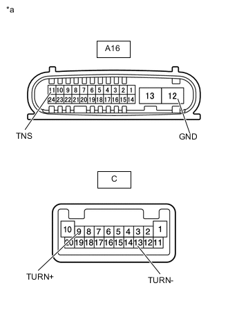
*a Component without harness connected
(Headlight ECU sub-assembly LH)
Measure the resistance according to the value(s) in the table below.
Standard Resistance Tester Connection Condition Specified Condition A16-11 (TNS) - C-9 (TURN+) Always Below 1 Ω A16-12 (GND) - C-13 (TURN-) Always Below 1 Ω A16-11 (TNS) - A16-12 (GND) Always 10 kΩ or higher Result Proceed to OK NG
OK
REPLACE COMBINATION METER ASSEMBLY Click here
NG
REPLACE HEADLIGHT ECU SUB-ASSEMBLY Click here
-
-
CHECK HARNESS AND CONNECTOR (HEADLIGHT ASSEMBLY LH - COMBINATION METER ASSEMBLY OR BODY GROUND)
-
Disconnect the A11 headlight assembly LH connector.
-
Disconnect the F5 combination meter assembly connector.
-
Measure the resistance according to the value(s) in the table below.
Standard Resistance (Check for Open) Tester Connection Condition Specified Condition A11-4 (B) - F5-13 (LL) Always Below 1 Ω A11-6 (E) - Body ground Always Below 1 Ω Standard Resistance (Check for Short) Tester Connection Condition Specified Condition A11-4 (B) - Body ground Always 10 kΩ or higher Result Proceed to OK NG
OK
REPLACE COMBINATION METER ASSEMBLY Click here
NG
REPAIR OR REPLACE HARNESS OR CONNECTOR
-
-
CHECK HARNESS AND CONNECTOR (COMBINATION METER ASSEMBLY - OUTER REAR VIEW MIRROR ASSEMBLY LH OR BODY GROUND)
-
Disconnect the F5 combination meter assembly connector.
-
Disconnect the J7*1 or J11*2 outer rear view mirror assembly LH connector.
-
Measure the resistance according to the value(s) in the table below.
Standard Resistance (Check for Open) Tester Connection Condition Specified Condition J7-1 (B) - F5-13 (LL)*1 Always Below 1 Ω J11-16 (B) - F5-13 (LL)*2 Always Below 1 Ω J7-2 (E) - Body ground*1 Always Below 1 Ω J11-12 - Body ground*2 Always Below 1 Ω Standard Resistance (Check for Short) Tester Connection Condition Specified Condition J7-1 (B) - Body ground*1 Always 10 kΩ or higher J11-16 (B) - Body ground*2 Always 10 kΩ or higher
-
*1: for TMC Made
-
*2: for TMMT Made
Result Proceed to OK NG -
OK
REPLACE COMBINATION METER ASSEMBLY Click here
NG
REPAIR OR REPLACE HARNESS OR CONNECTOR
-
-
CHECK HARNESS AND CONNECTOR (REAR COMBINATION LIGHT ASSEMBLY LH - COMBINATION METER ASSEMBLY OR BODY GROUND)
-
Disconnect the M48 rear combination light assembly LH connector.
-
Disconnect the F5 combination meter assembly connector.
-
Measure the resistance according to the value(s) in the table below.
Standard Resistance (Check for Open) Tester Connection Condition Specified Condition F5-6 (TRNL) - M48-4 (TRN) Always Below 1 Ω M48-3 (E) - Body ground Always Below 1 Ω Standard Resistance (Check for Short) Tester Connection Condition Specified Condition M48-4 (TRN) - Body ground Always 10 kΩ or higher Result Proceed to OK NG
OK
REPLACE COMBINATION METER ASSEMBLY Click here
NG
REPAIR OR REPLACE HARNESS OR CONNECTOR
-