LIGHTING SYSTEM Ambient Illumination Light Circuit
DESCRIPTION
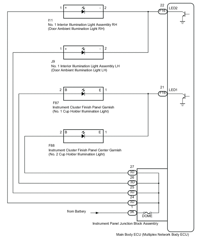
The main body ECU (multiplex network body ECU) controls the ambient illumination lights.
WIRING DIAGRAM
CAUTION / NOTICE / HINT
Note
-
Inspect the lights for circuits related to this system before performing the following procedure.
-
Before replacing the main ECU (multiplex network body ECU), refer to Service Bulletin*1.
-
*1: w/ Entry and Start System
PROCEDURE
-
PERFORM ACTIVE TEST USING GTS
-
Connect the GTS to the DLC3.
-
Turn the ignition switch to ON.
-
Turn the GTS on.
-
Enter the following menus: Body Electrical / Main Body / Active Test.
-
Perform the Active Test according to the display on the GTS.
Body Electrical > Main Body > Active TestTester Display Measurement Item Control Range Diagnostic Note Interior Illumination Light1
-
Cup holder illumination light
-
Door ambient illumination light
ON or OFF Preconditions for using the Active Test to check dimmer controlled illumination:
-
for CVT
-
Ignition switch ON.
-
Shift lever is in any position other than P.
-
for Manual Transaxle
-
Ignition switch ON.
-
Parking brake released.
-
The vehicle speed is more than 3 km/h (1.9 mph)
Interior Illumination Light2
-
Cup holder illumination light
-
Door ambient illumination light
ON or OFF Preconditions for using the Active Test to check dimmer controlled illumination:
-
for CVT
-
Ignition switch ON.
-
Shift lever is in any position other than P.
-
for Manual Transaxle
-
Ignition switch ON.
-
Parking brake released.
-
The vehicle speed is more than 3 km/h (1.9 mph)
Body Electrical > Main Body > Active TestTester Display Interior Illumination Light1
Body Electrical > Main Body > Active TestTester Display Interior Illumination Light2 OK Ambient illumination lights comes on. Result Result Proceed to OK A NG (All ambient lights do not illuminate) B NG (Cup holder illumination light does not illuminate) C NG (Door ambient illumination light does not illuminate) D -
A 
PROCEED TO NEXT SUSPECTED AREA SHOWN IN PROBLEM SYMPTOMS TABLE Click here
C 
INSPECT INSTRUMENT PANEL JUNCTION BLOCK ASSEMBLY Click here
D
INSPECT INSTRUMENT PANEL JUNCTION BLOCK ASSEMBLY Click here
B 
-
-
CHECK HARNESS AND CONNECTOR (POWER SOURCE - INSTRUMENT PANEL JUNCTION BLOCK ASSEMBLY)
-
Disconnect the 3K instrument panel junction block assembly connector.
-
Measure the voltage according to the value(s) in the table below.
Standard Voltage Tester Connection Condition Specified Condition 3K-1 - Body ground Always 11 to 14 V Result Proceed to OK NG
NG
REPAIR OR REPLACE HARNESS OR CONNECTOR
OK
-
-
INSPECT INSTRUMENT PANEL JUNCTION BLOCK ASSEMBLY
-
Disconnect the 3D instrument panel junction block assembly connector.
-
Measure the resistance according to the value(s) in the table below.
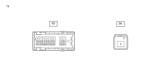
*a Component without harness connected
(Instrument Panel Junction Block Assembly)
- - Standard Resistance Tester Connection Condition Specified Condition 3K-1 - 3D-24 Always Below 1 Ω 3K-1 - 3D-25 Always Below 1 Ω 3K-1 - 3D-26 Always Below 1 Ω 3K-1 - 3D-27 Always Below 1 Ω Result Result Proceed to OK A NG (for LHD) B NG (for RHD) C
A
PROCEED TO NEXT SUSPECTED AREA SHOWN IN PROBLEM SYMPTOMS TABLE Click here
B
REPLACE INSTRUMENT PANEL JUNCTION BLOCK ASSEMBLY Click here
C
REPLACE INSTRUMENT PANEL JUNCTION BLOCK ASSEMBLY Click here
-
-
INSPECT INSTRUMENT PANEL JUNCTION BLOCK ASSEMBLY
-
Disconnect the 3D instrument panel junction block assembly connector.
-
Disconnect the 3K instrument panel junction block assembly connector.
-
Measure the resistance according to the value(s) in the table below.
*a Component without harness connected
(Instrument Panel Junction Block Assembly)
- - Standard Resistance Tester Connection Condition Specified Condition 3K-1 - 3D-26 Always Below 1 Ω 3K-1 - 3D-27 Always Below 1 Ω Result Result Proceed to OK A NG (for LHD) B NG (for RHD) C
B
REPLACE INSTRUMENT PANEL JUNCTION BLOCK ASSEMBLY Click here
C
REPLACE INSTRUMENT PANEL JUNCTION BLOCK ASSEMBLY Click here
A
-
-
CHECK HARNESS AND CONNECTOR (INSTRUMENT CLUSTER FINISH PANEL GARNISH - INSTRUMENT PANEL JUNCTION BLOCK ASSEMBLY)
-
Disconnect the F87 instrument cluster finish panel garnish connector.
-
Disconnect the F88 instrument cluster finish panel center garnish connector.
-
Measure the resistance according to the value(s) in the table below.
Standard Resistance Tester Connection Condition Specified Condition F87-2 (B) - 3D-26 Always Below 1 Ω F88-2 (B) - 3D-27 Always Below 1 Ω F87-2 (B) or 3D-26 - Body ground Always 10 kΩ or higher F88-2 (B) or 3D-27 - Body ground Always 10 kΩ or higher Result Proceed to OK NG
NG
REPAIR OR REPLACE HARNESS OR CONNECTOR
OK
-
-
CHECK HARNESS AND CONNECTOR (INSTRUMENT CLUSTER FINISH PANEL GARNISH - MAIN BODY ECU (MULTIPLEX NETWORK BODY ECU))
-
Disconnect the F16 main body ECU (multiplex network body ECU) connector.
-
Measure the resistance according to the value(s) in the table below.
Standard Resistance Tester Connection Condition Specified Condition F87-1 (E) - F16-21(LED1) Always Below 1 Ω F88-1 (E) - F16-21 (LED1) Always Below 1 Ω F87-1 (E) or F16-21(LED1) - Body ground Always 10 kΩ or higher F88-1 (E) or F16-21 (LED1) - Body ground Always 10 kΩ or higher Result Result Proceed to OK (for LHD) A OK (for RHD) B NG C
A
REPLACE MAIN BODY ECU (MULTIPLEX NETWORK BODY ECU) Click here
B
REPLACE MAIN BODY ECU (MULTIPLEX NETWORK BODY ECU) Click here
C
REPAIR OR REPLACE HARNESS OR CONNECTOR
-
-
INSPECT INSTRUMENT PANEL JUNCTION BLOCK ASSEMBLY
-
Disconnect the instrument panel junction block assembly connectors.
-
Measure the resistance according to the value(s) in the table below.
*a Component without harness connected
(Instrument Panel Junction Block Assembly)
- - Standard Resistance Tester Connection Condition Specified Condition 3K-1 - 3D-24 Always Below 1 Ω 3K-1 - 3D-25 Always Below 1 Ω Result Result Proceed to OK A NG (for LHD) B NG (for RHD) C
B
REPLACE INSTRUMENT PANEL JUNCTION BLOCK ASSEMBLY Click here
C
REPLACE INSTRUMENT PANEL JUNCTION BLOCK ASSEMBLY Click here
A
-
-
CHECK HARNESS AND CONNECTOR (NO. 1 INTERIOR ILLUMINATION LIGHT ASSEMBLY - INSTRUMENT PANEL JUNCTION BLOCK ASSEMBLY)
-
Disconnect the I11 No. 1 interior illumination light assembly RH connector.
-
Disconnect the J9 No. 1 interior illumination light assembly LH connector.
-
Measure the resistance according to the value(s) in the table below.
Standard Resistance Tester Connection Condition Specified Condition I11-1 (+) - 3D-24 Always Below 1 Ω I11-1 (+) or 3D-24 - Body ground Always 10 kΩ or higher J9-1 (+) - 3D-25 Always Below 1 Ω J9-1 (+) or 3D-25 - Body ground Always 10 kΩ or higher Result Proceed to OK NG
NG
REPAIR OR REPLACE HARNESS OR CONNECTOR
OK
-
-
CHECK HARNESS AND CONNECTOR (NO. 1 INTERIOR ILLUMINATION LIGHT ASSEMBLY - MAIN BODY ECU (MULTIPLEX NETWORK BODY ECU))
-
Disconnect the F16 main body ECU (multiplex network body ECU) connector.
-
Measure the resistance according to the value(s) in the table below.
Standard Resistance Tester Connection Condition Specified Condition I11-2 (-) - F16-22 (LED2) Always Below 1 Ω I11-2 (-) or F16-22 (LED2) - Body ground Always 10 kΩ or higher J9-2 (-) - F16-22 (LED2) Always Below 1 Ω J9-2 (-) or F16-22 (LED2) - Body ground Always 10 kΩ or higher Result Result Proceed to OK (for LHD) A OK (for RHD) B NG C
A
REPLACE MAIN BODY ECU (MULTIPLEX NETWORK BODY ECU) Click here
B
REPLACE MAIN BODY ECU (MULTIPLEX NETWORK BODY ECU) Click here
C
REPAIR OR REPLACE HARNESS OR CONNECTOR
-