IMMOBILISER SYSTEM(w/ Entry and Start System), Diagnostic DTC:B2784
| DTC Code | DTC Name |
|---|---|
| B2784 | Antenna Coil Open / Short |
DESCRIPTION
When an open or short circuit is detected in the transponder key amplifier coil built into the engine switch, the certification ECU (smart key ECU assembly) stores this DTC. This DTC is also stored as a history DTC.
| DTC No. | Detection Item | DTC Detection Condition | Trouble Area | Note |
|---|---|---|---|---|
| B2784 | Antenna Coil Open / Short | When either of the following conditions is met (1-trip detection logic*1):
|
|
DTC output confirmation operation:
|
-
*1: Only output while a malfunction is present.
-
*2: for CVT
| Vehicle Condition | |||
|---|---|---|---|
| Pattern 1 | Pattern 2 | ||
| Diagnosis Condition | Always | ○ | ○ |
| Malfunction Status | The transponder key amplifier coil built into the engine switch is open (determined by communication with certification ECU (smart key ECU assembly)). | ○ | - |
| The transponder key amplifier coil built into the engine switch is shorted (determined by communication with certification ECU (smart key ECU assembly)). | - | ○ | |
| Detection Time | - | - | |
| Number of Trips | 1 trip | 1 trip | |
| Vehicle Condition when Malfunction Detected | Fail-safe Operation when Malfunction Detected |
|---|---|
| Engine cannot be started when transmitter battery is depleted by holding electrical key transmitter sub-assembly near engine switch and pressing and holding engine switch with shift lever in P*1 | - |
-
*1: for CVT
| DTC No. | Data List and Active Test |
|---|---|
| B2784 | - |
WIRING DIAGRAM

| *a | CODE |
| *b | Engine Switch |
| *c | Certification ECU (Smart Key ECU Assembly) |
CAUTION / NOTICE / HINT
Note
-
When using the GTS with the engine switch off, connect the GTS to the DLC3 and turn a courtesy light switch on and off at intervals of 1.5 seconds or less until communication between the GTS and the vehicle begins. Then select the vehicle type under manual mode and enter the following menus: Body Electrical / Entry&Start(CAN). While using the GTS, periodically turn a courtesy light switch on and off at intervals of 1.5 seconds or less to maintain communication between the GTS and the vehicle.
-
Before replacing the certification ECU (smart key ECU assembly), refer to Service Bulletin.
-
After performing repairs, confirm that no DTCs are output by performing "DTC Output Confirmation Operation".
PROCEDURE
-
CLEAR DTC
-
Clear the DTCs.
Body Electrical > Entry&Start > Clear DTCsResult Proceed to NEXT
NEXT 
-
-
CHECK FOR DTC
-
Perform "DTC Output Confirmation Operation" procedure.
-
Check for DTCs.
Body Electrical > Entry&Start > Trouble CodesOK DTC B2784 is not output. Result Proceed to OK NG
OK 
USE SIMULATION METHOD TO CHECK Click here
NG
-
-
CHECK ENGINE SWITCH (OUTPUT)
-
Using an oscilloscope, check the waveform.
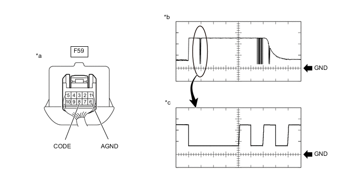
*a Component with harness connected
(Engine Switch)
*b Waveform *c Waveform (detail) - - Measurement Condition Tester Connection Condition Tool Setting Specified Condition F59-8 (CODE) - F59-6 (AGND) Engine switch off, engine switch pressed with electrical key transmitter sub-assembly held near engine switch* 1 V/DIV., 20 ms./DIV. Pulse generation
(See waveform)
2 V/DIV., 100 μs./DIV. Pulse generation
(See waveform (detail))
-
*: Remove the transmitter battery before performing this inspection.
OK The waveform is similar to that shown in the illustration Result Proceed to Proceed to OK A NG (for 8NR-FTS with LHD) B NG (for 8NR-FTS with RHD) C NG (for 3ZR-FAE) D -
B
REPLACE ENGINE SWITCH Click here
C
REPLACE ENGINE SWITCH Click here
D
REPLACE ENGINE SWITCH Click here
A
-
-
REPLACE CERTIFICATION ECU (SMART KEY ECU ASSEMBLY)
-
Replace the certification ECU (smart key ECU assembly) with a new one.
Tech Tips
Refer to Service Bulletin.
Result Proceed to NEXT
NEXT
-
-
REGISTER ECU COMMUNICATION ID
-
Register the ECU communication ID code.
Tech Tips
Refer to Service Bulletin.
Result Proceed to NEXT
NEXT
-
-
CLEAR DTC
-
Clear the DTCs.
Body Electrical > Entry&Start > Clear DTCsResult Proceed to NEXT
NEXT
-
-
CHECK FOR DTC
-
Perform "DTC Output Confirmation Operation" procedure.
-
Check for DTCs.
Body Electrical > Entry&Start > Trouble CodesOK DTC B2784 is not output. Result Proceed to Proceed to OK A NG (for 8NR-FTS with LHD) B NG (for 8NR-FTS with RHD) C NG (for 3ZR-FAE) D
A
END (CERTIFICATION ECU (SMART KEY ECU ASSEMBLY) WAS DEFECTIVE)
B
REPLACE ENGINE SWITCH Click here
C
REPLACE ENGINE SWITCH Click here
D
REPLACE ENGINE SWITCH Click here
-