ENTRY AND START SYSTEM(for Start Function) Engine does not Start
DESCRIPTION
When the electrical key transmitter sub-assembly is in the cabin and the engine switch is pressed, the certification ECU (smart key ECU assembly) receives a signal and changes the power source mode. Additionally, when the shift lever is in P*1 and the brake pedal*1 or clutch pedal*2 is depressed, the engine can be started by pressing the engine switch. If the steering is unlocked, the engine can also be started by pressing the engine switch with the shift lever in N*1 and the brake pedal*1 or clutch pedal*2 depressed.
-
*1: for CVT
-
*2: for Manual Transaxle
| Problem Symptom | Data List and Active Test |
|---|---|
| Engine does not start |
Power Source Control
Entry&Start
Starting Control |
-
*1: for CVT
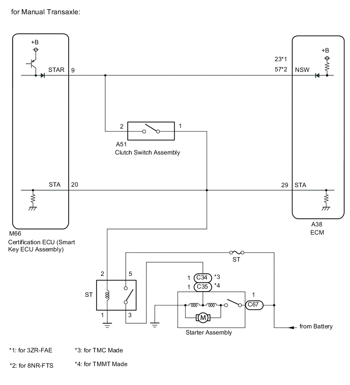
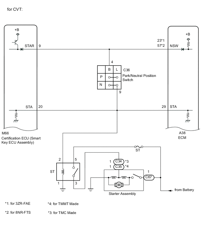
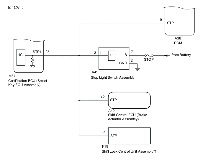
WIRING DIAGRAM
CAUTION / NOTICE / HINT
Note
-
When using the GTS with the engine switch off, connect the GTS to the DLC3 and turn a courtesy light switch on and off at intervals of 1.5 seconds or less until communication between the GTS and the vehicle begins. Then select Model Code "KEY REGIST" under manual mode and enter the following menus: Body Electrical / Entry&Start(CAN). While using the GTS, periodically turn a courtesy light switch on and off at intervals of 1.5 seconds or less to maintain communication between the GTS and the vehicle.
-
The entry and start system (for Start Function) uses the LIN communication system and CAN communication system. Inspect the communication function by following How to Proceed with Troubleshooting. Troubleshoot the entry and start system (for Start Function) after confirming that the communication systems are functioning properly.
-
If the entry and start system (for Start Function) has been canceled, enable the system before performing troubleshooting.
-
Inspect the fuses of circuits related to this system before performing the following procedure.
-
Before replacing the certification ECU (smart key ECU assembly) or an electrical key transmitter sub-assembly, refer to entry and start system (for Start Function) Precaution.
-
After completing repairs, confirm that the problem does not recur.
Tech Tips
-
When the cable is disconnected and reconnected to the negative (-) battery terminal, the power source mode returns to the state it was in before the cable was disconnected.
-
If the engine switch is turned from on (IG) to on (ACC) with the shift lever in any position other than P, and then the shift lever is moved to P and the engine switch is pressed with the brake pedal depressed, the engine switch will turn off.*1
-
If the brake pedal is repeatedly depressed while the engine is stopped, the brake booster pressure will be released and the force required to depress the brake pedal to illuminate the stop lights will increase.*1
-
*1: for CVT
-
The certification ECU (smart key ECU assembly) stores the operation history of the entry and start system and it can be read using the GTS.
Body Electrical > Entry&Start > Utility
| Tester Display |
|---|
| Operation History |
| Parameter Name | Content |
|---|---|
| Operating Engine Switch / Key RF Signal Interference | When the engine switch was operated, the electrical key transmitter sub-assembly could not be confirmed due to wave interference. |
| Parameter Name | Content |
|---|---|
| Operating Engine Switch / Key LF Signal Interference | When the engine switch was operated, the electrical key transmitter sub-assembly could not be verified because it was excessively close to an indoor electrical key antenna assembly or because a tool or transmitter other than a registered electrical key transmitter sub-assembly was used. |
PROCEDURE
-
CHECK ELECTRICAL KEY TRANSMITTER SUB-ASSEMBLY
-
Press a switch of the electrical key transmitter sub-assembly.
OK The electrical key transmitter sub-assembly LED illuminates. Result Proceed to OK NG
NG 
INSPECT TRANSMITTER BATTERY Click here
OK 
-
-
READ VALUE USING GTS (KEY LOW BATTERY)
-
Connect the GTS to the DLC3.
-
Turn the engine switch on (IG).
-
Turn the GTS on.
-
Enter the following menus: Body Electrical / Entry&Start / Data List.
-
Read the Data List according to the display on the GTS.
Body Electrical > Entry&Start > Data ListTester Display Measurement Item Range Normal Condition Diagnostic Note Key Low Battery Transmitter battery depleted No or Yes No: Transmitter battery not depleted
Yes: Transmitter battery depleted
The electrical key transmitter sub-assembly sends voltage information to the certification ECU (smart key ECU assembly) when it is transmitting. "Yes" is displayed for the Data List item "Key Low Battery" when this voltage information indicates 2.2 V or less. This Data List item should be checked when the electrical key transmitter sub-assembly is at room temperature (example: at -20°C (-4°F), "Yes" may be displayed even if the transmitter battery is new).
Body Electrical > Entry&Start > Data ListTester Display Key Low Battery Result Result Proceed to "No" is displayed on the GTS screen A "Yes" is displayed on the GTS screen B
B 
REPLACE TRANSMITTER BATTERY Click here
A
-
-
CHECK ENGINE CRANK
-
Get into the vehicle while carrying the electrical key transmitter.
-
Move the shift lever to P.*1
-
Depress the brake pedal*1 or clutch pedal*2.
-
Press the engine switch and check that the engine cranks.
-
*1: for CVT
-
*2: for Manual Transaxle
Result Result Proceed to Engine cranks, but there is no initial combustion or engine is difficult to start A Engine does not cranks B -
B
CHECK FOR DTC Click here
A
-
-
CHECK HARNESS AND CONNECTOR (CERTIFICATION ECU (SMART KEY ECU ASSEMBLY) - ECM)
-
Disconnect the M66 certification ECU (smart key ECU assembly) connector.
-
Disconnect the A38 ECM connector.
-
Disconnect the A51 clutch switch assembly connector.*1
-
Disconnect the C36 park/neutral position switch connector.*2
-
Remove the ST relay.
-
Measure the resistance according to the value(s) in the table below.
-
*1: for Manual Transaxle
-
*2: for CVT
Standard Resistance Tester Connection Condition Specified Condition M66-20 (STA) - A38-29 (STA) Always Below 1 Ω M66-20 (STA) or A38-29 (STA) - Body ground Always 10 kΩ or higher Result Proceed to OK NG -
NG
REPAIR OR REPLACE HARNESS OR CONNECTOR
OK
-
-
CHECK CONNECTOR CONNECTION CONDITION
-
Disconnect the M66 certification ECU (smart key ECU assembly) connector.
-
Connect the M66 certification ECU (smart key ECU assembly) connector.
-
Press the engine switch and check that the engine starts.
OK Engine starts. Result Proceed to OK NG
OK
CONNECT SECURELY
NG
GO TO IMMOBILISER SYSTEM Click here
-
-
CHECK FOR DTC
-
Using the GTS, check for certification ECU (smart key ECU assembly) DTCs.
Body Electrical > Entry&Start > Trouble Codes
Body Electrical > Starting Control > Trouble Codes
Body Electrical > Power Source Control > Trouble CodesResult Result Proceed to DTCs are not output A Entry and start system (for Start Function) DTCs are output B
B
GO TO DIAGNOSTIC TROUBLE CODE CHART Click here
A
-
-
CHECK ENGINE SWITCH CONDITION
-
Get into the vehicle while carrying an electrical key transmitter sub-assembly.
-
Move the shift lever to P.*1
-
With the brake pedal*1 or clutch pedal*2 released, check that pressing the engine switch causes the power source mode to change.
-
*1: for CVT
-
*2: for Manual Transaxle
Result Result Proceed to Power source mode changes : Off → on (ACC) → on (IG) → off A Power source mode does not change to on (ACC) or on (IG) B Power source mode changes to on (IG) but not to on (ACC) C Power source mode changes to on (ACC) but not to on (IG) D -
B
GO TO POWER SOURCE MODE DOES NOT CHANGE TO ON (IG AND ACC) Click here
C
GO TO POWER SOURCE MODE DOES NOT CHANGE TO ON (ACC) Click here
D
GO TO POWER SOURCE MODE DOES NOT CHANGE TO ON (IG) Click here
A
-
-
READ VALUE USING GTS (STOP LIGHT SWITCH1, NEUTRAL SW/ CLUTCH SW)
-
for CVT
-
Connect the GTS to the DLC3.
-
Turn the engine switch on (IG).
-
Turn the GTS on.
-
Enter the following menus: Body Electrical / Power Source Control / Data List.
-
According to the display on the GTS, read the Data List.
Body Electrical > Power Source Control > Data ListTester Display Measurement Item Range Normal Condition Diagnostic Note Stop Light Switch1 State of brake pedal OFF or ON OFF: Brake pedal released
ON: Brake pedal depressed
-
Use this item to determine if the stop light switch assembly is malfunctioning.
-
The engine cannot be started when this item is OFF.
-
If the stop light switch assembly is malfunctioning, the engine can be started by pressing and holding the engine switch for a certain period of time.
Body Electrical > Power Source Control > Data ListTester Display Stop Light Switch1 OK The item in the Data List changes when the brake pedal is depressed and released. -
-
-
for Manual Transaxle
-
Connect the GTS to the DLC3.
-
Turn the engine switch on (IG).
-
Turn the GTS on.
-
Enter the following menus: Body Electrical / Power Source Control / Data List.
-
According to the display on the GTS, read the Data List.
Body Electrical > Power Source Control > Data ListTester Display Measurement Item Range Normal Condition Diagnostic Note Neutral SW/ Clutch SW State of clutch pedal OFF or ON OFF: Clutch pedal released
ON: Clutch pedal depressed
-
Use this item to help determine if the clutch position switch is malfunctioning.
-
The engine cannot be started when this item is "OFF".
Body Electrical > Power Source Control > Data ListTester Display Neutral SW/ Clutch SW OK The item in the Data List changes when the clutch pedal is depressed and released. -
Result Result Proceed to OK (for CVT) A OK (for Manual Transaxle) B NG (for CVT) C NG (for Manual Transaxle) D -
B
GO TO STEP 10 Click here
C
INSPECT STOP LIGHT SWITCH ASSEMBLY Click here
D
INSPECT CLUTCH SWITCH ASSEMBLY Click here
A
-
-
READ VALUE USING GTS (NEUTRAL SW/ CLUTCH SW, SHIFT POSITION P OR N)
-
Connect the GTS to the DLC3.
-
Turn the engine switch on (IG).
-
Turn the GTS on.
-
Enter the following menus: Body Electrical / Power Source Control or Starting Control / Data List.
-
According to the display on the GTS, read the Data List.
Body Electrical > Power Source Control > Data ListTester Display Measurement Item Range Normal Condition Diagnostic Note Neutral SW/ Clutch SW Shift position (P and N) OFF or ON OFF: Shift lever not in P or N
ON: Shift lever in P or N
-
Use this item to determine whether the park/neutral start switch assembly is malfunctioning.
-
When the engine cannot be started due to a park/neutral start switch assembly malfunction, "OFF" is displayed.
Body Electrical > Power Source Control > Data ListTester Display Neutral SW/ Clutch SW
Body Electrical > Starting Control > Data ListTester Display Measurement Item Range Normal Condition Diagnostic Note Shift Position P or N Park/neutral position switch status OFF or ON OFF: Shift lever in any position other than P or N
ON: Shift lever in P or N
When OFF is displayed, the engine will not crank.
Body Electrical > Starting Control > Data ListTester Display Shift Position P or N OK The item in the Data List changes according to the shift position. Result Proceed to OK NG -
NG
INSPECT PARK/NEUTRAL POSITION SWITCH Click here
OK
-
-
READ VALUE USING GTS (STARTER REQUEST SIGNAL)
-
Connect the GTS to the DLC3.
-
Turn the engine switch on (IG).
-
Turn the GTS on.
-
Enter the following menus: Body Electrical / Power Source Control / Data List.
-
According to the display on the GTS, read the Data List.
Body Electrical > Power Source Control > Data ListTester Display Measurement Item Range Normal Condition Diagnostic Note Starter Request Signal Engine start request signal status OFF or ON
-
OFF: The engine switch is not pressed
-
ON: With the shift lever in P and the brake pedal depressed, the engine switch is pressed and held
for CVT
-
OFF: The engine switch is not pressed
-
ON: With the clutch pedal depressed, the engine switch is pressed and held
for Manual Transaxle
-
When the engine cannot be started due to a start request signal malfunction, OFF is displayed.
-
When the engine switch is pressed, the duration of time that ON is displayed will be extremely short. As such, the engine switch needs to be pressed and held for a certain period of time.
Body Electrical > Power Source Control > Data ListTester Display Starter Request Signal Note
Check that the key warning light is illuminated in green on the combination meter assembly, and then press the engine switch.
OK The display changes in response to the operation of the engine switch. Result Proceed to OK NG -
NG
CHECK STEERING LOCK SYSTEM Click here
OK
-
-
READ VALUE USING GTS (STARTER SW)
-
Connect the GTS to the DLC3.
-
Turn the engine switch on (IG).
-
Turn the GTS on.
-
Enter the following menus: Body Electrical / Starting Control / Data List.
-
Get into the vehicle while carrying the electrical key transmitter sub-assembly, move the shift lever to P*1, press the engine switch while depressing the brake pedal*1 or clutch pedal*2 and confirm that the Data List item changes.
-
*1: for CVT
-
*2: for Manual Transaxle
Body Electrical > Starting Control > Data ListTester Display Measurement Item Range Normal Condition Diagnostic Note Starter SW Starter operation request OFF or ON OFF: Starter operation not requested
ON: Starter operation requested
When OFF is displayed, the engine will not crank.
Body Electrical > Starting Control > Data ListTester Display Starter SW OK The Data List item changes. Result Proceed to OK NG -
NG
REPLACE CERTIFICATION ECU (SMART KEY ECU ASSEMBLY)
OK
-
-
READ VALUE USING GTS (STARTER RELAY)
-
Connect the GTS to the DLC3.
-
Turn the engine switch on (IG).
-
Turn the GTS on.
-
Enter the following menus: Body Electrical / Starting Control / Data List.
-
According to the display on the GTS, read the Data List.
Body Electrical > Starting Control > Data ListTester Display Measurement Item Range Normal Condition Diagnostic Note Starter Relay Starter relay voltage monitor OFF or ON OFF: ST relay off
ON: ST relay on
When OFF is displayed the engine cannot be cranked.
Body Electrical > Starting Control > Data ListTester Display Starter Relay Result Proceed to OK NG
NG
INSPECT ST RELAY Click here
OK
-
-
CHECK CONNECTOR CONNECTION CONDITION
-
Disconnect the M66 certification ECU (smart key ECU assembly) connector.
-
Connect the M66 certification ECU (smart key ECU assembly) connector.
-
Press the engine switch and check that the engine starts.
OK Engine starts. Result Proceed to OK NG
OK
CONNECT SECURELY
NG
REPLACE CERTIFICATION ECU (SMART KEY ECU ASSEMBLY)
-
-
INSPECT TRANSMITTER BATTERY
-
Inspect the transmitter battery.
Note
Do not wrap the lead wire ground a terminal, wedge it between terminals, or solder it. The terminal may be deformed or damaged, and the transmitter battery will not be able to be installed correctly.
Result Proceed to OK NG
OK
REPLACE ELECTRICAL KEY TRANSMITTER SUB-ASSEMBLY
NG
REPLACE TRANSMITTER BATTERY Click here
-
-
INSPECT ST RELAY
-
Remove the ST relay.
-
Inspect the ST relay.
-
for 8NR-FTS: Click here
-
for 3ZR-FAE: Click here
Result Proceed to OK NG -
NG
REPLACE ST RELAY
OK
-
-
CHECK HARNESS AND CONNECTOR (CERTIFICATION ECU (SMART KEY ECU ASSEMBLY) - BODY GROUND)
-
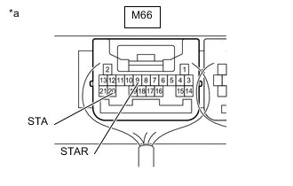
*a Front view of wire harness connector
(to Certification ECU (Smart Key ECU Assembly))
Disconnect the M66 certification ECU (smart key ECU assembly) connector.
-
Disconnect the A38 ECM connector.
-
Move the shift lever to P or N.*1
-
*1: for CVT
-
-
Measure the resistance according to the value(s) in the table below.
Standard Resistance Tester Connection Condition Specified Condition M66-20 (STA) - Body ground 20°C (68°F) 101.69 to 153.84 Ω M66-9 (STAR) - Body ground Result Result Proceed to OK A NG (for CVT) B NG (for Manual Transaxle) C
B
CHECK HARNESS AND CONNECTOR (CERTIFICATION ECU (SMART KEY ECU ASSEMBLY) - PARK/NEUTRAL POSITION SWITCH) Click here
C
CHECK HARNESS AND CONNECTOR (CERTIFICATION ECU (SMART KEY ECU ASSEMBLY) - CLUTCH SWITCH ASSEMBLY) Click here
A
-
-
INSPECT STARTER ASSEMBLY
-
Remove the starter assembly.
-
for 8NR-FTS:
-
for Valeo Made Cold Area Specification Vehicles: Click here
-
for Denso Made without Stop and Start System: Click here
-
for Valeo Made except Cold Area Specification Vehicles: Click here
-
for 3ZR-FAE: Click here
-
-
Inspect the starter assembly.
-
for 8NR-FTS:
-
for Valeo Made Cold Area Specification Vehicles: Click here
-
for Denso Made without Stop and Start System: Click here
-
for Valeo Made except Cold Area Specification Vehicles: Click here
-
for 3ZR-FAE: Click here
Result Result Proceed to OK A NG (for 8NR-FTS with Valeo Made Cold Area Specification Vehicles) B NG (for 8NR-FTS with Denso Made without Stop and Start System) C NG (for 8NR-FTS with Valeo Made except Cold Area Specification Vehicles) D NG (for 3ZR-FAE) E -
B
REPLACE STARTER ASSEMBLY Click here
C
REPLACE STARTER ASSEMBLY Click here
D
REPLACE STARTER ASSEMBLY Click here
E
REPLACE STARTER ASSEMBLY Click here
A
-
-
CHECK HARNESS AND CONNECTOR (BATTERY - STARTER AND ST RELAY)
-
Remove the starter assembly from the vehicle to perform an inspection.
-
for 8NR-FTS:
-
for Valeo Made Cold Area Specification Vehicles: Click here
-
for Denso Made without Stop and Start System: Click here
-
for Valeo Made except Cold Area Specification Vehicles: Click here
-
for 3ZR-FAE: Click here
-
-
Remove the ST relay.
-
Measure the voltage according to the value(s) in the table below.
Standard Voltage Tester Connection Condition Specified Condition C67-1 - Body ground Always 11 to 14 V ST relay terminal 5 - Body ground Always 11 to 14 V -
Measure the resistance according to the value(s) in the table below.
Standard Resistance Tester Connection Condition Specified Condition ST relay terminal 3 - C34-1*1 Always Below 1 Ω ST relay terminal 3 - C35-1*2 Always Below 1 Ω ST relay terminal 3 or C34-1 - Body ground*1 Always 10 kΩ or higher ST relay terminal 3 or C35-1 - Body ground*2 Always 10 kΩ or higher
-
*1: for TMC Made
-
*2: for TMMT Made
Result Proceed to OK NG -
OK
REPLACE CERTIFICATION ECU (SMART KEY ECU ASSEMBLY)
NG
REPAIR OR REPLACE HARNESS OR CONNECTOR
-
-
CHECK HARNESS AND CONNECTOR (CERTIFICATION ECU (SMART KEY ECU ASSEMBLY) - PARK/NEUTRAL POSITION SWITCH)
-
Disconnect the M66 certification ECU (smart key ECU assembly) connector.
-
Disconnect the C36 park/neutral position switch connector.
-
Disconnect the A38 ECM connector.
-
Measure the resistance according to the value(s) in the table below.
Standard Resistance Tester Connection Condition Specified Condition M66-9 (STAR) - C36-4 (B) Always Below 1 Ω M66-9 (STAR) or C36-4 (B) Always 10 kΩ or higher Result Proceed to OK NG
NG
REPAIR OR REPLACE HARNESS OR CONNECTOR
OK
-
-
CHECK HARNESS AND CONNECTOR (PARK/NEUTRAL POSITION SWITCH - ST RELAY)
-
Disconnect the C36 park/neutral position switch connector.
-
Remove the ST relay.
-
Disconnect the M66 certification ECU (smart key ECU assembly) connector.
-
Disconnect the A38 ECM connector.
-
Measure the resistance according to the value(s) in the table below.
Standard Resistance Tester Connection Condition Specified Condition C36-9 (L) - ST relay terminal 2 Always Below 1 Ω C36-9 (L) or ST relay terminal 2 - Body ground Always 10 kΩ or higher Result Proceed to OK NG
NG
REPAIR OR REPLACE HARNESS OR CONNECTOR
OK
-
-
CHECK HARNESS AND CONNECTOR (CERTIFICATION ECU (SMART KEY ECU ASSEMBLY) - ST RELAY)
-
Disconnect the M66 certification ECU (smart key ECU assembly) connector.
-
Disconnect the A38 ECM connector.
-
Disconnect the C36 park/neutral position switch connector.
-
Remove the ST relay.
-
Measure the resistance according to the value(s) in the table below.
Standard Resistance Tester Connection Condition Specified Condition M66-20 (STA) - ST relay terminal 2 Always Below 1 Ω M66-20 (STA) or ST relay terminal 2 - Body ground Always 10 kΩ or higher Result Proceed to OK NG
NG
REPAIR OR REPLACE HARNESS OR CONNECTOR
OK
-
-
CHECK HARNESS AND CONNECTOR (ST RELAY - BODY GROUND)
-
Remove the ST relay.
-
Measure the resistance according to the value(s) in the table below.
Standard Resistance Tester Connection Condition Specified Condition ST relay terminal 1 - Body ground Always Below 1 Ω Result Proceed to OK NG
NG
REPAIR OR REPLACE HARNESS OR CONNECTOR
OK
-
-
CHECK CONNECTOR CONNECTION CONDITION
-
Disconnect the M66 certification ECU (smart key ECU assembly) connector.
-
Connect the M66 certification ECU (smart key ECU assembly) connector.
-
Press the engine switch and check that the engine starts.
OK Engine starts. Result Proceed to OK NG
OK
CONNECT SECURELY
NG
REPLACE CERTIFICATION ECU (SMART KEY ECU ASSEMBLY)
-
-
CHECK HARNESS AND CONNECTOR (CERTIFICATION ECU (SMART KEY ECU ASSEMBLY) - CLUTCH SWITCH ASSEMBLY)
-
Disconnect the M66 certification ECU (smart key ECU assembly) connector.
-
Disconnect the A51 clutch switch assembly connector.
-
Disconnect the A38 ECM connector.
-
Measure the resistance according to the value(s) in the table below.
Standard Resistance Tester Connection Condition Specified Condition M66-9 (STAR) - A51-2 Always Below 1 Ω M66-9 (STAR) or A51-2 - Body ground Always 10 kΩ or higher Result Proceed to OK NG
NG
REPAIR OR REPLACE HARNESS OR CONNECTOR
OK
-
-
CHECK HARNESS AND CONNECTOR (CLUTCH SWITCH ASSEMBLY - ST RELAY)
-
Disconnect the A51 clutch switch assembly connector.
-
Remove the ST relay.
-
Disconnect the M66 certification ECU (smart key ECU assembly) connector.
-
Disconnect the A38 ECM connector.
-
Measure the resistance according to the value(s) in the table below.
Standard Resistance Tester Connection Condition Specified Condition A51-1 - ST relay terminal 2 Always Below 1 Ω A51-1 or ST relay terminal 2 - Body ground Always 10 kΩ or higher Result Proceed to OK NG
NG
REPAIR OR REPLACE HARNESS OR CONNECTOR
OK
-
-
CHECK HARNESS AND CONNECTOR (CERTIFICATION ECU (SMART KEY ECU ASSEMBLY) - ST RELAY)
-
Disconnect the M66 certification ECU (smart key ECU assembly) connector.
-
Disconnect the A38 ECM connector.
-
Remove the ST relay.
-
Measure the resistance according to the value(s) in the table below.
Standard Resistance Tester Connection Condition Specified Condition M66-20 (STA) - ST relay terminal 2 Always Below 1 Ω M66-20 (STA) or ST relay terminal 2 - Body ground Always 10 kΩ or higher Result Proceed to OK NG
NG
REPAIR OR REPLACE HARNESS OR CONNECTOR
OK
-
-
CHECK HARNESS AND CONNECTOR (ST RELAY - BODY GROUND)
-
Remove the ST relay.
-
Measure the resistance according to the value(s) in the table below.
Standard Resistance Tester Connection Condition Specified Condition ST relay terminal 1 - Body ground Always Below 1 Ω Result Proceed to OK NG
NG
REPAIR OR REPLACE HARNESS OR CONNECTOR
OK
-
-
CHECK CONNECTOR CONNECTION CONDITION
-
Disconnect the M66 certification ECU (smart key ECU assembly) connector.
-
Connect the M66 certification ECU (smart key ECU assembly) connector.
-
Press the engine switch and check that the engine starts.
OK Engine starts. Result Proceed to OK NG
OK
CONNECT SECURELY
NG
REPLACE CERTIFICATION ECU (SMART KEY ECU ASSEMBLY)
-
-
CHECK STEERING LOCK SYSTEM
-
Check that the steering unlocks when the engine switch is turned on (ACC).
OK The steering unlocks. Result Proceed to OK NG
NG
GO TO STEERING LOCK SYSTEM (PROBLEM SYMPTOMS TABLE) Click here
OK
-
-
CHECK SECURITY INDICATOR LIGHT (IMMOBILISER SYSTEM UNSET)
-
Get into the vehicle while carrying an electrical key transmitter sub-assembly.
-
Move the shift lever to P.*1
-
Press the engine switch with the brake pedal*1 or clutch pedal*2 released and check that the security indicator light changes from blinking to off at the same time that the power source mode changes to on (ACC).
-
*1: for CVT
-
*2: for Manual Transaxle
Tech Tips
It is determined that the immobiliser function is operating correctly if the security indicator light changes from blinking to off at the same time that the power source mode changes to on (ACC).
OK Security indicator light changes from blinking to off at the same time that the power source mode changes to on (ACC). Result Proceed to OK NG -
OK
REPLACE CERTIFICATION ECU (SMART KEY ECU ASSEMBLY)
NG
GO TO IMMOBILISER SYSTEM (PROBLEM SYMPTOMS TABLE) Click here
-
-
INSPECT PARK/NEUTRAL POSITION SWITCH
-
Remove the park/neutral position switch.
-
for K114: Click here
-
for K313: Click here
-
for K313F: Click here
-
-
Inspect the park/neutral position switch.
-
for K114: Click here
-
for K313: Click here
-
for K313F: Click here
Result Result Proceed to OK A NG (for K114) B NG (for K313) C NG (for K313F) D -
B
REPLACE PARK/NEUTRAL POSITION SWITCH Click here
C
REPLACE PARK/NEUTRAL POSITION SWITCH Click here
D
REPLACE PARK/NEUTRAL POSITION SWITCH Click here
A
-
-
CHECK HARNESS AND CONNECTOR (CERTIFICATION ECU (SMART KEY ECU ASSEMBLY) - PARK/NEUTRAL POSITION SWITCH)
-
Disconnect the M66 certification ECU (smart key ECU assembly) connector.
-
Disconnect the C36 park/neutral position switch connector.
-
Disconnect the A38 ECM connector.
-
Measure the resistance according to the value(s) in the table below.
Standard Resistance Tester Connection Condition Specified Condition M66-9 (STAR) - C36-4 (B) Always Below 1 Ω M66-9 (STAR) or C36-4 (B) Always 10 kΩ or higher Result Proceed to OK NG
OK
REPLACE CERTIFICATION ECU (SMART KEY ECU ASSEMBLY)
NG
REPAIR OR REPLACE HARNESS OR CONNECTOR
-
-
INSPECT STOP LIGHT SWITCH ASSEMBLY
-
Remove the stop light switch assembly.
-
Inspect the stop light switch assembly.
Result Proceed to OK NG
NG
REPLACE STOP LIGHT SWITCH ASSEMBLY Click here
OK
-
-
CHECK HARNESS AND CONNECTOR (STOP LIGHT SWITCH ASSEMBLY - POWER SUPPLY AND BODY GROUND)
-
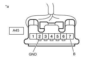
*a Front view of wire harness connector
(to Stop Light Switch Assembly)
Disconnect the stop light switch assembly connector.
-
Measure the voltage according to the value(s) in the table below.
Standard Voltage Tester Connection Condition Specified Condition A45-7 (B) - Body ground Always 11 to 14 V -
Measure the resistance according to the value(s) in the table below.
Standard Resistance Tester Connection Condition Specified Condition A45-2 (GND) - Body ground Always Below 1 Ω Result Proceed to OK NG
NG
REPAIR OR REPLACE HARNESS OR CONNECTOR
OK
-
-
CHECK HARNESS AND CONNECTOR (CERTIFICATION ECU (SMART KEY ECU ASSEMBLY) - STOP LIGHT SWITCH ASSEMBLY)
-
Disconnect the M67 certification ECU (smart key ECU assembly) connector.
-
Disconnect the A38 ECM connector.
-
Disconnect the A42 skid control ECU (brake actuator assembly) connector.
-
Disconnect the F19 shift lock control unit assembly connector.
-
Measure the resistance according to the value(s) in the table below.
Standard Resistance Tester Connection Condition Specified Condition M67-25 (STP1) - A45-3 (L) Always Below 1 Ω M67-25 (STP1) or A45-3 (L) - Body ground Always 10 kΩ or higher Result Proceed to OK NG
OK
REPLACE CERTIFICATION ECU (SMART KEY ECU ASSEMBLY)
NG
REPAIR OR REPLACE HARNESS OR CONNECTOR
-
-
INSPECT CLUTCH SWITCH ASSEMBLY
-
Remove the clutch switch assembly.
-
Inspect the clutch switch assembly.
Result Proceed to OK NG
NG
REPLACE CLUTCH SWITCH ASSEMBLY Click here
OK
-
-
CHECK HARNESS AND CONNECTOR (CERTIFICATION ECU (SMART KEY ECU ASSEMBLY) - CLUTCH SWITCH ASSEMBLY)
-
Disconnect the M66 certification ECU (smart key ECU assembly) connector.
-
Disconnect the A51 clutch switch assembly connector.
-
Disconnect the A38 ECM connector.
-
Measure the resistance according to the value(s) in the table below.
Standard Resistance Tester Connection Condition Specified Condition M66-9 (STAR) - A51-2 Always Below 1 Ω M66-9 (STAR) or A51-2 - Body ground Always 10 kΩ or higher Result Proceed to OK NG
OK
REPLACE CERTIFICATION ECU (SMART KEY ECU ASSEMBLY)
NG
REPAIR OR REPLACE HARNESS OR CONNECTOR
-