WIRELESS DOOR LOCK CONTROL SYSTEM(w/o Entry and Start System) TERMINALS OF ECU
-
CHECK INSTRUMENT PANEL JUNCTION BLOCK ASSEMBLY AND MAIN BODY ECU (MULTIPLEX NETWORK BODY ECU)
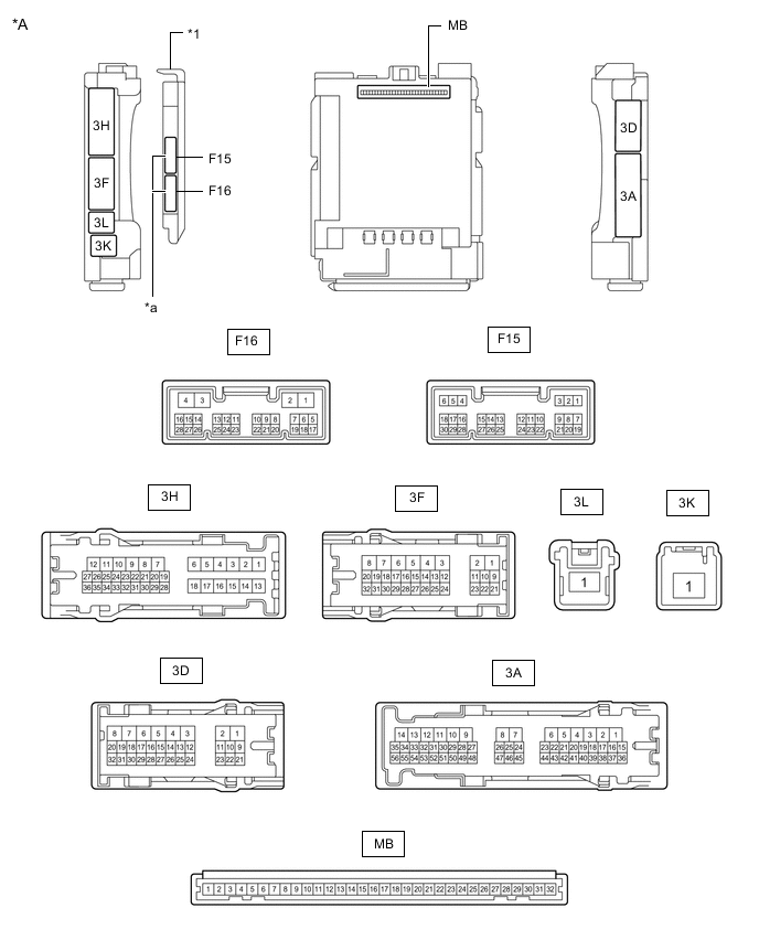
*A Main Body ECU (Multiplex Network Body ECU) with 2 Connectors - - *1 Main Body ECU (Multiplex Network Body ECU) - - *a 2 Connectors - - 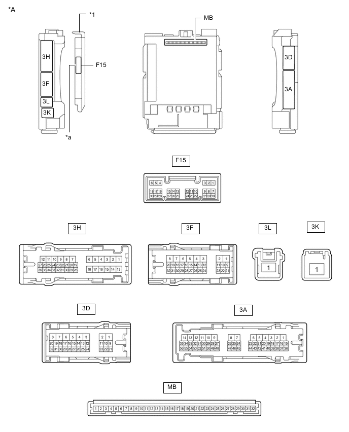
*A Main Body ECU (Multiplex Network Body ECU) with 1 Connector - - *1 Main Body ECU (Multiplex Network Body ECU) - - *a 1 Connector - -
-
Remove the main body ECU (multiplex network body ECU) from the instrument panel junction block assembly.
-
for LHD: Click here
-
for RHD: Click here
-
-
Reconnect the instrument panel junction block assembly connectors.
-
Measure the resistance and voltage according to the value(s) in the table below.
Terminal No. (Symbol) Wiring Color Terminal Description Condition Specified Condition MB-11 (GND1) - Body ground - Ground Always Below 1 Ω MB-31 (BECU) - Body ground - Battery power supply Always 11 to 14 V MB-30 (ACC) - Body ground - ACC power supply Ignition switch ACC 11 to 14 V MB-30 (ACC) - Body ground - ACC power supply Ignition switch off Below 1 V MB-32 (IG) - Body ground - IG power supply Ignition switch ON 11 to 14 V MB-32 (IG) - Body ground - IG power supply Ignition switch off Below 1 V -
Install the main body ECU (multiplex network body ECU) to the instrument panel junction block assembly.
-
for LHD: Click here
-
for RHD: Click here
-
-
Measure the voltage according to the value(s) in the table below.
Tester Connection Wiring Color Terminal Description Condition Specified Condition 3H-8 (ACT-) - Body ground LA-B - Body ground Door lock motor unlock drive output Door control switch or driver door key cylinder off Below 1 V 3H-8 (ACT-) - Body ground LA-B - Body ground Door lock motor unlock drive output Door control switch or driver door key cylinder unlocked 11 to 14 V 3H-9 (ACT-) - Body ground B - Body ground Door lock motor unlock drive output Door control switch or driver door key cylinder off Below 1 V 3H-9 (ACT-) - Body ground B - Body ground Door lock motor unlock drive output Door control switch or driver door key cylinder unlocked 11 to 14 V 3H-6 (ACT+) - Body ground R - Body ground Door lock motor lock drive output Door control switch or driver door key cylinder off Below 1 V 3H-6 (ACT+) - Body ground R - Body ground Door lock motor lock drive output Door control switch or driver door key cylinder locked 11 to 14 V 3H-18 (ACT+) - Body ground R - Body ground Door lock motor lock drive output Door control switch or driver door key cylinder off Below 1 V 3H-18 (ACT+) - Body ground R - Body ground Door lock motor lock drive output Door control switch or driver door key cylinder locked 11 to 14 V 3D-4 (ACTD) - Body ground B - Body ground*1
L - Body ground*2
Door lock motor unlock drive output Door control switch or driver door key cylinder off → on (unlock) Below 1 V → 11 to 14 V → Below 1 V F15-6 (FLCY) - Body ground R - Body ground Front door courtesy light switch (for LH) input Front door LH open Below 1 V F15-6 (FLCY) - Body ground R - Body ground Front door courtesy light switch (for LH) input Front door LH closed Pulse generation F15-27 (FRCY) - Body ground BR - Body ground Front door courtesy light switch (for RH) input Front door RH open Below 1 V F15-27 (FRCY) - Body ground BR - Body ground Front door courtesy light switch (for RH) input Front door RH closed Pulse generation 3H-24 (LCTY) - Body ground BR - Body ground Rear door courtesy light switch (for LH) input Rear door LH open Below 1 V 3H-24 (LCTY) - Body ground BR - Body ground Rear door courtesy light switch (for LH) input Rear door LH closed Pulse generation 3A-31 (RCTY) - Body ground BR - Body ground Rear door courtesy light switch (for RH) input Rear door RH open Below 1 V 3A-31 (RCTY) - Body ground BR - Body ground Rear door courtesy light switch (for RH) input Rear door RH closed Pulse generation 3D-13 (LSFL) - Body ground B - Body ground Front door LH unlock detection switch input Front door LH unlocked Below 1 V 3D-13 (LSFL) - Body ground B - Body ground Front door LH unlock detection switch input Front door LH locked Pulse generation 3D-12 (LSFR) - Body ground*3 or *4 GR - Body ground Front door RH unlock detection switch input Front door RH unlocked Below 1 V 3D-12 (LSFR) - Body ground*3 or *4 GR - Body ground Front door RH unlock detection switch input Front door RH locked Pulse generation 3D-14 (LSR) - Body ground*3 LG - Body ground Rear door LH/RH unlock detection switch input Rear door LH or RH unlocked Below 1 V 3D-14 (LSR) - Body ground*3 LG - Body ground Rear door LH/RH unlock detection switch input Rear door LH and RH locked Pulse generation F15-5 (PRG) - Body ground GR - Body ground Signal output to door control receiver Key inserted into ignition key cylinder → Key pulled out of ignition key cylinder 11 to 14 V → Pulse generation → 11 to 14 V F15-4 (RDA) - Body ground LG - Body ground Signal input from door control receiver Ignition switch off, all doors closed and door control transmitter assembly switch not pressed 11 to 14 V Ignition switch off, all doors closed and door control transmitter assembly switch pressed Pulse generation
(0 to 12 V)
3A-41 (KSW) - Body ground V - Body ground Key unlock warning switch input No key in ignition key cylinder Pulse generation 3A-41 (KSW) - Body ground V - Body ground Key unlock warning switch input Key in ignition key cylinder Below 1 V
-
*1: for LHD
-
*2: for RHD
-
*3: w/ Double Locking System
-
*4: for RHD w/o Double Locking System
If the result is not as specified, the main body ECU (multiplex network body ECU) or instrument panel junction block assembly may be malfunctioning.
-
-
-
CHECK DOOR CONTROL RECEIVER (w/ Tire Pressure Warning System)
-
Disconnect the M23 door control receiver connector.

-
Measure the voltage and resistance according to the value(s) in the table below.
Tech Tips
Measure the values on the wire harness side with the connectors disconnected.
Tester Connection Wiring Color Terminal Description Condition Specified Condition M23-7 (+B) - Body ground R - Body ground Battery power supply Always 11 to 14 V M23-12 (GND) - Body ground W-B - Body ground Ground Always Below 1 Ω -
Reconnect the M23 door control receiver connector.
-
Measure the voltage according to the value(s) in the table below.
Terminal No. (Symbol) Wiring Color Terminal Description Condition Specified Condition M23-5 (PRG) - M23-12 (GND) W - W-B Signal input from main body ECU (multiplex network body ECU) Key inserted into ignition key cylinder → Key pulled out of ignition key cylinder 11 to 14 V → Pulse generation → 11 to 14 V M23-4 (RDA) - M23-12 (GND) G - W-B Signal output to main body ECU (multiplex network body ECU) Ignition switch off, all doors closed and door control transmitter assembly switch not pressed 11 to 14 V Ignition switch off, all doors closed and door control transmitter assembly switch pressed Pulse generation
(0 to 12 V)
-
-
CHECK DOOR CONTROL RECEIVER (w/o Tire Pressure Warning System)
-
Disconnect the M30 door control receiver connector.

-
Measure the voltage and resistance according to the value(s) in the table below.
Tech Tips
Measure the values on the wire harness side with the connectors disconnected.
Terminal No. (Symbol) Wiring Color Terminal Description Condition Specified Condition M30-5 (+B) - Body ground R - Body ground Battery power supply Always 11 to 14 V M30-1 (GND) - Body ground W-B - Body ground Ground Always Below 1 Ω -
Reconnect the M30 door control receiver connector.
-
Measure the voltage according to the value(s) in the table below.
Terminal No. (Symbol) Wiring Color Terminal Description Condition Specified Condition M30-3 (PRG) - M30-1 (GND) W - W-B Signal input from main body ECU (multiplex network body ECU) Key inserted into ignition key cylinder → Key pulled out of ignition key cylinder 11 to 14 V → Pulse generation → 11 to 14 V M30-2 (RDA) - M30-1 (GND) G - W-B Signal output to main body ECU (multiplex network body ECU) Ignition switch off, all doors closed and door control transmitter assembly switch not pressed 11 to 14 V Ignition switch off, all doors closed and door control transmitter assembly switch pressed Pulse generation
(0 to 12 V)
-