WIRELESS DOOR LOCK CONTROL SYSTEM(w/ Entry and Start System), Diagnostic DTC:B1242
| DTC Code | DTC Name |
|---|---|
| B1242 | Wireless Door Lock Tuner Circuit Malfunction |
DESCRIPTION
The door control receiver is used to receive radio waves related to the entry functions of the electrical key transmitter sub-assembly. The certification ECU (smart key ECU assembly) decodes the requested electrical key transmitter sub-assembly operation by identifying a key code based on the radio waves received via the door control receiver. The door control receiver receives a signal from the electrical key transmitter sub-assembly and sends signals to the main body ECU (multiplex network body ECU) through the certification ECU (smart key ECU assembly). (ex. If a door lock operation is requested, the certification ECU (smart key ECU assembly) sends a door lock command to the main body ECU (multiplex network body ECU)).
| DTC No. | Detection Item | DTC Detection Condition | Trouble Area |
|---|---|---|---|
| B1242 | Wireless Door Lock Tuner Circuit Malfunction |
|
|
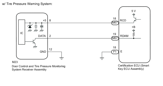
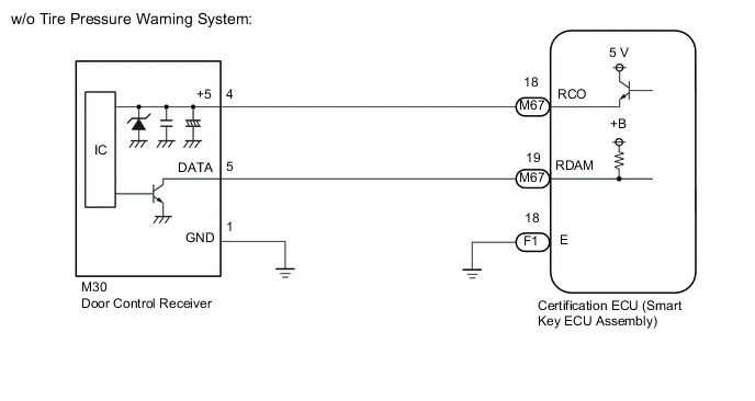
WIRING DIAGRAM
CAUTION / NOTICE / HINT
Note
-
When replacing or inspecting the door control receiver and wire harness, do not change the position or length of the wire harness. If the wire harness is too close to the door control receiver, the performance of the entry function and wireless function may be affected.
-
This DTC is not stored within 10 seconds of the engine switch being turned from on (IG) to off.
-
The wireless door lock control system uses the CAN communication system. Inspect the communication function by following How to Proceed with Troubleshooting. Troubleshoot the wireless door lock control system after confirming that the communication system is functioning properly.
-
Before replacing the certification ECU (smart key ECU assembly), refer to Service Bulletin.
-
When replacing the door control receiver, read the transmitter IDs (tire pressure warning system) stored in the old ECU using the GTS and write them down before removal.*
-
It is necessary to perform initialization (Click here) after registration Click here of the transmitter IDs into the door control receiver if the door control receiver has been replaced.*
-
*: w/ Tire Pressure Warning System
PROCEDURE
-
CHECK CERTIFICATION ECU (SMART KEY ECU ASSEMBLY)
-
Disconnect the M23*1 or M30*2 door control receiver connector.
-
*1: w/ Tire Pressure Warning System
-
*2: w/o Tire Pressure Warning System
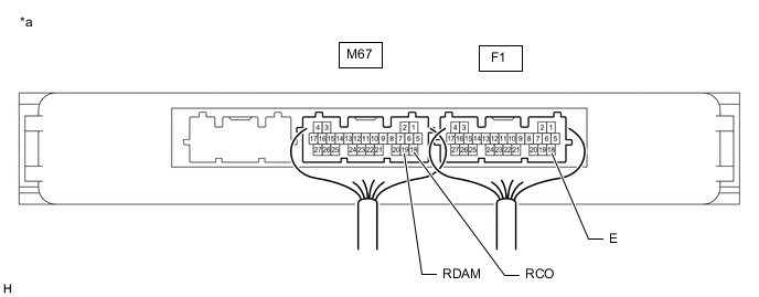
*a Component with harness connected
(Certification ECU (Smart Key ECU Assembly))
- - -
-
Measure the voltage and resistance and check for pulses according to the value(s) in the table below.
Standard Voltage Tester Connection Condition Specified Condition M67-19 (RDAM) - F1-18 (E) Engine switch off 11 to 14 V M67-18 (RCO) - F1-18 (E) always Below 1 V → 4.5 to 5.5 V pulse generation at regular intervals Standard Resistance Tester Connection Condition Specified Condition F1-18 (E) - Body ground Always Below 1 Ω Result Proceed to OK NG
OK 
REPLACE ELECTRICAL KEY AND TPMS RECEIVER ASSEMBLY Click here
NG 
-
-
CHECK HARNESS AND CONNECTOR (DOOR CONTROL RECEIVER - CERTIFICATION ECU (SMART KEY ECU ASSEMBLY))
-
Disconnect the F1 and M67 certification ECU (smart key ECU assembly) connectors.
-
Measure the resistance according to the value(s) in the table below.
Standard Resistance w/ Tire Pressure Warning System Tester Connection Condition Specified Condition M67-19 (RDAM) - M23-2 (DATA) Always Below 1 Ω M67-18 (RCO) - M23-8 (+5) Always Below 1 Ω M23-12 (GND) - Body ground Always Below 1 Ω M23-2 (DATA) or M67-19 (RDAM) - Body ground Always 10 kΩ or higher M23-8 (+5) or M67-18 (RCO) - Body ground Always 10 kΩ or higher Standard Resistance w/o Tire Pressure Warning System Tester Connection Condition Specified Condition M67-19 (RDAM) - M30-5 (DATA) Always Below 1 Ω M67-18 (RCO) - M30-4 (+5) Always Below 1 Ω M30-1 (GND) - Body ground Always Below 1 Ω M30-5 (DATA) or M67-19 (RDAM) - Body ground Always 10 kΩ or higher M30-4 (+5) or M67-18 (RCO) - Body ground Always 10 kΩ or higher Result Proceed to OK NG
OK
REPLACE CERTIFICATION ECU (SMART KEY ECU ASSEMBLY)
NG
REPAIR OR REPLACE HARNESS OR CONNECTOR
-