POWER DOOR LOCK CONTROL SYSTEM Only Back Door cannot be Opened
DESCRIPTION
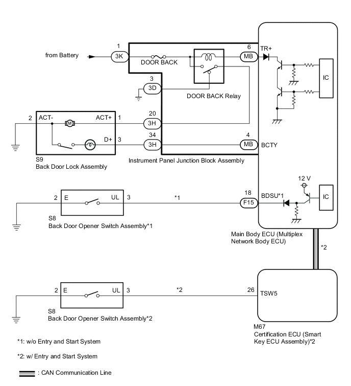
The main body ECU (multiplex network body ECU) receives signals from the back door opener switch assembly. When a signal received is the main body ECU (multiplex network body ECU) activates the back door lock motor.
WIRING DIAGRAM
CAUTION / NOTICE / HINT
Note
-
Before replacing the main body ECU (multiplex network body ECU), refer to Service Bulletin*.
-
*: w/ Entry and Start System
-
The power door lock control system uses the CAN communication system. Inspect the communication function by following How to Proceed with Troubleshooting. Troubleshoot the power door lock control system after confirming that the communication systems are functioning properly.*
-
*: w/ Entry and Start System
-
Before performing this troubleshooting procedure, perform troubleshooting for the entry and start system (for Entry Function) (Back Door Entry Unlock Function does not Operate) first.*
-
*: w/ Entry and Start System
PROCEDURE
-
CONFIRM MODEL
-
Choose the model to be inspected.
Result Result Proceed to w/ Entry and Start System A w/o Entry and Start System B
B 
CHECK POWER DOOR LOCK OPERATION (BASIC FUNCTION) Click here
A 
-
-
INSPECT BACK DOOR LOCK ASSEMBLY
-
Remove the back door lock assembly.
-
Inspect the back door lock assembly.
Result Proceed to OK NG
NG 
REPLACE BACK DOOR LOCK ASSEMBLY Click here
OK
-
-
CHECK HARNESS AND CONNECTOR (BACK DOOR LOCK ASSEMBLY - INSTRUMENT PANEL JUNCTION BLOCK ASSEMBLY)
-
Disconnect the 3H instrument panel junction block assembly connector.
-
Measure the resistance according to the value(s) in the table below.
Standard Resistance Tester Connection Condition Specified Condition S9-1 (ACT+) - 3H-20 Always Below 1 Ω S9-3 (D+) - 3H-34 Always Below 1 Ω S9-2 (ACT-) - Body ground Always Below 1 Ω S9-1 (ACT+) or 3H-20 - Body ground Always 10 kΩ or higher S9-3 (D+) or 3H-34 - Body ground Always 10 kΩ or higher Result Proceed to OK NG
NG
REPAIR OR REPLACE HARNESS OR CONNECTOR
OK
-
-
INSPECT INSTRUMENT PANEL JUNCTION BLOCK ASSEMBLY
-
Remove the instrument panel junction block assembly.
-
for LHD: Click here
-
for RHD: Click here
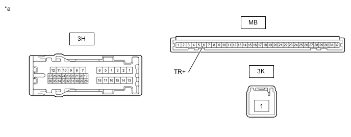
*a Component without harness connected
(Instrument Panel Junction Block Assembly)
- - -
-
Remove the main body ECU (multiplex network body ECU) from the instrument panel junction block assembly.
-
Measure the voltage according to the value(s) in the table below.
Standard Resistance Tester Connection Condition Specified Condition 3H-20 - Body ground Battery voltage not applied between 3K-1 and MB-6 (TR+) Below 1 V 3H-20 - Body ground Battery voltage applied between 3K-1 and MB-6 (TR+) 11 to 14 V Result Result Proceed to OK A NG (for LHD) B NG (for RHD) C
B
REPLACE INSTRUMENT PANEL JUNCTION BLOCK ASSEMBLY Click here
C
REPLACE INSTRUMENT PANEL JUNCTION BLOCK ASSEMBLY Click here
A
-
-
CHECK BACK DOOR OPEN OPERATION
-
Check that the back door can be opened.
OK The back door can be opened. Result Result Proceed to OK A NG (for LHD) B NG (for RHD) C
A
END
B
REPLACE MAIN BODY ECU (MULTIPLEX NETWORK BODY ECU) Click here
C
REPLACE MAIN BODY ECU (MULTIPLEX NETWORK BODY ECU) Click here
-
-
CHECK POWER DOOR LOCK OPERATION (BASIC FUNCTION)
-
Check the power door lock basic function.
OK The power door lock basic functions operate normally. Result Proceed to OK NG
NG
GO TO PROBLEM SYMPTOMS TABLE Click here
OK
-
-
READ VALUE USING GTS (Back Door Open)
-
Connect the GTS to the DLC3.
-
Turn the ignition switch to ON.
-
Turn the GTS on.
-
Enter the following menus: Body Electrical / Main Body / Data List.
-
Read the Data List according to the display on the GTS.
Body Electrical > Main Body > Data ListTester Display Measurement Item Range Normal Condition Diagnostic Note Back Door Open Back door lock signal Prohibt or Permit Prohibt: Back door locked
Permit: Back door unlocked
-
Body Electrical > Main Body > Data ListTester Display Back Door Open OK On the GTS screen, Prohibt or Permit is displayed accordingly. Result Result Proceed to OK A NG (for LHD) B NG (for RHD) C
B
REPLACE MAIN BODY ECU (MULTIPLEX NETWORK BODY ECU) Click here
C
REPLACE MAIN BODY ECU (MULTIPLEX NETWORK BODY ECU) Click here
A
-
-
PERFORM ACTIVE TEST USING GTS (Trunk and Back-Door Open)
-
Enter the following menus: Body Electrical / Main Body / Active Test.
-
Perform the Active Test according to the display on the GTS.
Body Electrical > Main Body > Active TestTester Display Measurement Item Control Range Diagnostic Note Trunk and Back-Door Open Back door lock motor OFF/ON -
Body Electrical > Main Body > Active TestTester Display Trunk and Back-Door Open OK The back door lock assembly operates normally. Result Proceed to OK NG
NG
INSPECT BACK DOOR LOCK ASSEMBLY Click here
OK
-
-
READ VALUE USING GTS (Back Door Open Handle SW)
-
Enter the following menus: Body Electrical / Main Body / Data List.
-
Read the Data List according to the display on the GTS.
Body Electrical > Main Body > Data ListTester Display Measurement Item Range Normal Condition Diagnostic Note Back Door Open Handle SW Back door opener switch signal OFF or ON OFF: Back door closed
ON: Back door open
-
Body Electrical > Main Body > Data ListTester Display Back Door Open Handle SW OK On the GTS screen, ON or OFF is displayed accordingly. Result Result Proceed to OK (for LHD) A OK (for RHD) B NG C
A
REPLACE MAIN BODY ECU (MULTIPLEX NETWORK BODY ECU) Click here
B
REPLACE MAIN BODY ECU (MULTIPLEX NETWORK BODY ECU) Click here
C
-
-
INSPECT BACK DOOR OPENER SWITCH ASSEMBLY
-
Remove the back door opener switch assembly.
-
Inspect the back door opener switch assembly.
Result Proceed to OK NG
NG
REPLACE BACK DOOR OPENER SWITCH ASSEMBLY Click here
OK
-
-
CHECK HARNESS AND CONNECTOR (BACK DOOR OPENER SWITCH ASSEMBLY - MAIN BODY ECU (MULTIPLEX NETWORK BODY ECU))
-
Disconnect the F15 main body ECU (multiplex network body ECU) connector.
-
Disconnect the S8 back door opener switch assembly connector.
-
Measure the resistance according to the value(s) in the table below.
Standard Resistance Tester Connection Condition Specified Condition F15-18 (BDSU) - S8-3 (UL) Always Below 1 Ω S8-2 (E) - Body ground Always Below 1 Ω F15-18 (BDSU) or S8-3 (UL) - Body ground Always 10 kΩ or higher Result Result Proceed to OK (for LHD) A OK (for RHD) B NG C
A
REPLACE MAIN BODY ECU (MULTIPLEX NETWORK BODY ECU) Click here
B
REPLACE MAIN BODY ECU (MULTIPLEX NETWORK BODY ECU) Click here
C
REPAIR OR REPLACE HARNESS OR CONNECTOR
-
-
INSPECT BACK DOOR LOCK ASSEMBLY
-
Remove the back door lock assembly.
-
Inspect the back door lock assembly.
Result Proceed to OK NG
NG
REPLACE BACK DOOR LOCK ASSEMBLY Click here
OK
-
-
CHECK HARNESS AND CONNECTOR (BACK DOOR LOCK ASSEMBLY - INSTRUMENT PANEL JUNCTION BLOCK ASSEMBLY)
-
Disconnect the 3H instrument panel junction block assembly connector.
-
Disconnect the S9 back door lock assembly connector.
-
Measure the resistance according to the value(s) in the table below.
Standard Resistance Tester Connection Condition Specified Condition S9-1 (ACT+) - 3H-20 Always Below 1 Ω S9-3 (D+) - 3H-34 Always Below 1 Ω S9-2 (ACT-) - Body ground Always Below 1 Ω S9-1 (ACT+) or 3H-20 - Body ground Always 10 kΩ or higher S9-3 (D+) or 3H-34 - Body ground Always 10 kΩ or higher Result Proceed to OK NG
NG
REPAIR OR REPLACE HARNESS OR CONNECTOR
OK
-
-
INSPECT INSTRUMENT PANEL JUNCTION BLOCK ASSEMBLY
-
Remove the instrument panel junction block assembly.
*a Component without harness connected
(Instrument Panel Junction Block Assembly)
- -
-
for LHD: Click here
-
for RHD: Click here
-
-
Remove the main body ECU (multiplex network body ECU) from the instrument panel junction block assembly.
-
Measure the voltage according to the value(s) in the table below.
Standard Resistance Tester Connection Condition Specified Condition 3H-20 - Body ground Battery voltage not applied between 3K-1 and MB-6 (TR+) Below 1 V 3H-20 - Body ground Battery voltage applied between 3K-1 and MB-6 (TR+) 11 to 14 V Result Result Proceed to OK A NG (for LHD) B NG (for RHD) C
B
REPLACE INSTRUMENT PANEL JUNCTION BLOCK ASSEMBLY Click here
C
REPLACE INSTRUMENT PANEL JUNCTION BLOCK ASSEMBLY Click here
A
-
-
CHECK BACK DOOR OPEN OPERATION
-
Check that the back door can be opened.
OK The back door can be opened. Result Result Proceed to OK A NG (for LHD) B NG (for RHD) C
A
END
B
REPLACE MAIN BODY ECU (MULTIPLEX NETWORK BODY ECU) Click here
C
REPLACE MAIN BODY ECU (MULTIPLEX NETWORK BODY ECU) Click here
-