POWER DOOR LOCK CONTROL SYSTEM TERMINALS OF ECU
-
CHECK INSTRUMENT PANEL JUNCTION BLOCK ASSEMBLY AND MAIN BODY ECU (MULTIPLEX NETWORK BODY ECU)
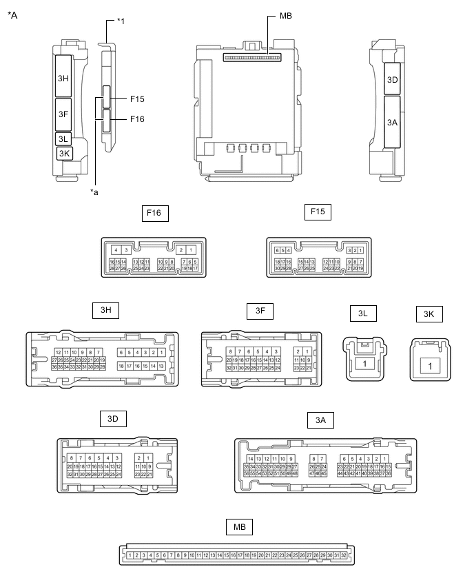
*A Main Body ECU (Multiplex Network Body ECU) with 2 Connectors - - *1 Main Body ECU (Multiplex Network Body ECU) - - *a 2 Connectors - - 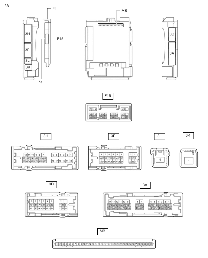
*A Main Body ECU (Multiplex Network Body ECU) with 1 Connector - - *1 Main Body ECU (Multiplex Network Body ECU) - - *a 1 Connector - -
-
Remove the main body ECU (multiplex network body ECU) from the instrument panel junction block assembly.
-
for LHD: Click here
-
for RHD: Click here
-
-
Reconnect the instrument panel junction block assembly connectors.
-
Measure the voltage and resistance according to the value(s) in the table below.
Terminal No. (Symbol) Wiring Color Terminal Description Condition Specified Condition MB-11 (GND1) - Body ground - Ground Always Below 1 Ω MB-30 (ACC) - Body ground - ACC power supply Ignition switch ACC 11 to 14 V MB-30 (ACC) - Body ground - ACC power supply Ignition switch off Below 1 V MB-31 (BECU) - Body ground - Battery power supply Always 11 to 14 V MB-32 (IG) - Body ground - IG power supply Ignition switch ON 11 to 14 V MB-32 (IG) - Body ground - IG power supply Ignition switch off Below 1 V -
Install the main body ECU (multiplex network body ECU) to the instrument panel junction block assembly.
-
for LHD: Click here
-
for RHD: Click here
-
-
Measure the voltage and check for pulses according to the value(s) in the table below.
Terminal No. (Symbol) Wiring Color Terminal Description Condition Specified Condition F15-2 (UL3) - Body ground L - Body ground Driver door key-linked unlock input Driver door key cylinder in neutral position → on (unlock) Pulse generation → Below 1 V F15-29 (L2) - Body ground G - Body ground Driver door key-linked lock input Driver door key cylinder in neutral position → on (lock) Pulse generation → Below 1 V F15-6 (FLCY) - Body ground R - Body ground Front door courtesy light switch (for LH) input Front door LH open Below 1 V F15-6 (FLCY) - Body ground R - Body ground Front door courtesy light switch (for LH) input Front door LH closed Pulse generation F15-27 (FRCY) - Body ground BR - Body ground Front door courtesy light switch (for RH) input Front door RH open Below 1 V F15-27 (FRCY) - Body ground BR - Body ground Front door courtesy light switch (for RH) input Front door RH closed Pulse generation 3H-8 (ACT-) - Body ground LA-B - Body ground Door lock motor unlock drive output Door control switch or driver door key cylinder off → on (unlock) Below 1 V → 11 to 14 V → Below 1 V 3H-9 (ACT-) - Body ground B - Body ground Door lock motor unlock drive output Door control switch or driver door key cylinder off → on (unlock) Below 1 V → 11 to 14 V → Below 1 V 3H-6 (ACT+) - Body ground R - Body ground Door lock motor lock drive output Door control switch or driver door key cylinder off → on (lock) Below 1 V → 11 to 14 V → Below 1 V 3H-18 (ACT+) - Body ground R - Body ground Door lock motor lock drive output Door control switch or driver door key cylinder off → on (lock) Below 1 V → 11 to 14 V → Below 1 V 3D-4 (ACTD) - Body ground B - Body ground*1
L - Body ground*2
Door lock motor unlock drive output Door control switch or driver door key cylinder off → on (unlock) Below 1 V → 11 to 14 V → Below 1 V 3H-24 (LCTY) - Body ground BR - Body ground Rear door courtesy light switch (for LH) input Rear door LH open Below 1 V 3H-24 (LCTY) - Body ground BR - Body ground Rear door courtesy light switch (for LH) input Rear door LH closed Pulse generation 3A-31 (RCTY) - Body ground BR - Body ground Rear door courtesy light switch (for RH) input Rear door RH open Below 1 V 3A-31 (RCTY) - Body ground BR - Body ground Rear door courtesy light switch (for RH) input Rear door RH closed Pulse generation 3H-34 (BCTY) - Body ground SB - Body ground Back door courtesy light switch input Back door open Below 1 V 3H-34 (BCTY) - Body ground SB - Body ground Back door courtesy light switch input Back door closed Pulse generation 3H-20 (TR+) - Body ground Y - Body ground Back door lock motor drive output Back door closed → open Below 1 V → 11 to 14 V → Below 1 V 3D-14 (LSR) - Body ground*3 or *4 LG - Body ground Rear door LH/RH unlock detection switch input Rear door LH or RH unlocked Below 1 V 3D-14 (LSR) - Body ground*3 or *4 LG - Body ground Rear door LH/RH unlock detection switch input Rear door LH and RH locked Pulse generation 3D-12 (LSFR) - Body ground*6 GR - Body ground Front door RH unlock detection switch input Front door RH unlocked Below 1 V 3D-12 (LSFR) - Body ground*6 GR - Body ground Front door RH unlock detection switch input Front door RH locked Pulse generation 3D-13 (LSFL) - Body ground B - Body ground Front door LH unlock detection switch input Front door LH unlocked Below 1 V 3D-13 (LSFL) - Body ground B - Body ground Front door LH unlock detection switch input Front door LH locked Pulse generation F15-18 (BDSU) - Body ground*5 LG - Body ground Back door opener switch input Back door opener switch pushed Below 1 V F15-18 (BDSU) - Body ground*5 LG - Body ground Back door opener switch input Back door opener switch not pushed Pulse generation
-
*1: for LHD
-
*2: for RHD
-
*3: w/ Double Locking System
-
*4: w/ Entry and Start System
-
*5: w/o Entry and Start System
-
*6: except for LHD without Double Locking System and without Entry and Start System
-
-
-
CHECK CERTIFICATION ECU (SMART KEY ECU ASSEMBLY) (w/ Entry and Start System)
-
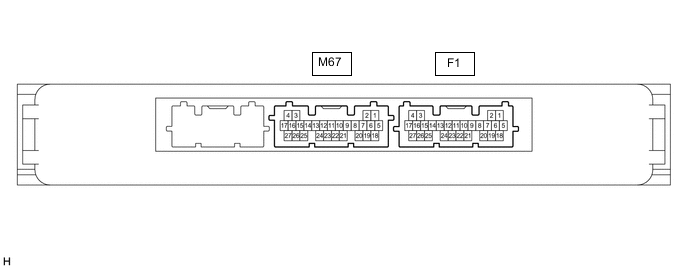
Disconnect the F1 certification ECU (smart key ECU assembly) connector.
-
Measure the voltage and resistance according to the value(s) in the table below.
Terminal No. (Symbol) Wiring Color Terminal Description Condition Specified Condition F1-4 (+B) - Body ground L - Body ground Battery power supply Ignition switch off 11 to 14 V F1-18 (E) - Body ground W-B - Body ground Ground Always Below 1 Ω -
Reconnect the M67 certification ECU (smart key ECU assembly) connector.
-
Check for pulses according to the value(s) in the table below.
Terminal No. (Symbol) Wiring Color Terminal Description Condition Specified Condition M67-26 (TSW5) - Body ground LG - Body ground Back door opener switch input Back door opener switch assembly (open switch) off → on Below 1 V → Pulse generation
-
-
CHECK DOUBLE LOCK DOOR CONTROL RELAY ASSEMBLY (w/ Double Locking System)

-
Disconnect the F14 double lock door control relay assembly connector.
-
Measure the voltage and resistance according to the value(s) in the table below.
Terminal No. (Symbol) Wiring Color Terminal Description Condition Specified Condition F14-12 (+B) - Body ground BE - Body ground Battery power supply Ignition switch off 11 to 14 V F14-11 (CPUB) - Body ground SB - Body ground Battery power supply Ignition switch off 11 to 14 V F14-7 (GND) - Body ground LA - Body ground Ground Always Below 1 Ω -
Reconnect the F14 double lock door control relay assembly connector.
-
Measure the voltage and check for pulses according to the value(s) in the table below.
Terminal No. (Symbol) Wiring Color Terminal Description Condition Specified Condition F14-8 (ACTS) - Body ground LG - Body ground All door double lock motor set on output Double lock unset Below 1 V F14-8 (ACTS) - Body ground LG - Body ground All door double lock motor set on output Double lock set 11 to 14 V F14-1 (ACTR) - Body ground GR - Body ground All door double lock motor set off output Double lock set Below 1 V F14-1 (ACTR) - Body ground GR - Body ground All door double lock motor set off output Double lock unset 11 to 14 V F14-6 (DLPD) - Body ground Y - Body ground Front RH double lock position switch input Double lock unset Pulse generation F14-6 (DLPD) - Body ground Y - Body ground Front RH double lock position switch input Double lock set Below 1 V F14-5 (DLPP) - Body ground V - Body ground Front LH double lock position switch input Double lock unset Pulse generation F14-5 (DLPP) - Body ground V - Body ground Front LH double lock position switch input Double lock set Below 1 V F14-4 (DLPR) - Body ground B - Body ground Rear RH double lock position switch input Double lock unset Pulse generation F14-4 (DLPR) - Body ground B - Body ground Rear RH double lock position switch input Double lock set Below 1 V F14-3 (DLPL) - Body ground L - Body ground Rear LH double lock position switch input Double lock unset Pulse generation F14-3 (DLPL) - Body ground L - Body ground Rear LH double lock position switch input Double lock set Below 1 V
-