CAN COMMUNICATION SYSTEM TERMINALS OF ECU
Note
-
After turning the ignition switch off, waiting time may be required before disconnecting the cable from the negative (-) battery terminal. Therefore, make sure to read the disconnecting the cable from the negative (-) battery terminal notices before proceeding with work.
-
Before measuring the resistance of the CAN bus, turn the ignition switch off and leave the vehicle for 1 minute or more without operating the key or any switches, or opening or closing the doors. After that, disconnect the cable from the negative (-) battery terminal and leave the vehicle for 1 minute or more before measuring the resistance.
-
This section describes the standard values for all CAN related components.
Tech Tips
-
The systems (ECUs and sensors) that use CAN communication vary depending on the vehicle and optional equipment. Check which systems (ECUs and sensors) are installed to the vehicle.
-
Operating the ignition switch, any other switches or a door triggers related ECU and sensor communication on the CAN. This communication will cause the resistance value to change.
-
Even after DTCs are cleared, if a DTC is stored again after driving the vehicle for a while, the malfunction may be occurring due to vibration of the vehicle. In such a case, wiggling the ECUs or wire harness while performing the inspection below may help determine the cause of the malfunction.
-
NO. 2 CAN JUNCTION CONNECTOR (w/o Blind Spot Monitor System)
-
Check the No. 2 CAN junction connector.
-
Connection diagram
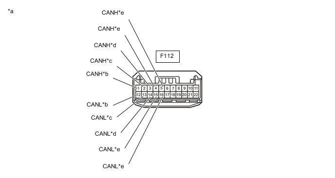
*a Front view of wire harness connector
(to No. 2 CAN Junction Connector)
*b to Clearance Warning ECU Assembly
(w/ TOYOTA Parking Assist-sensor System)
*c to Forward Recognition Camera
(w/ Toyota Safety Sense)
*d to Millimeter Wave Radar Sensor Assembly
(w/ Toyota Safety Sense)
*e to Central Gateway ECU (Network Gateway ECU) - - -
Check the connection diagram of the components which are connected to the No. 2 CAN junction connector.
Terminal No. (Symbol) Wiring Color Connected to F112-1 (CANH) SB Clearance warning ECU assembly*1
(for Bus 1)
F112-12 (CANL) GR F112-2 (CANH) R Forward recognition camera*2
(for Bus 1)
F112-13 (CANL) GR F112-3 (CANH) G Millimeter wave radar sensor assembly*2
(for Bus 1)
F112-14 (CANL) GR F112-4 (CANH) B Central gateway ECU (network gateway ECU)
(for Bus 1)
F112-15 (CANL) GR F112-5 (CANH) P Central gateway ECU (network gateway ECU)
(for Bus 1)
F112-16 (CANL) GR
-
*1: w/ TOYOTA Parking Assist-sensor System
-
*2: w/ Toyota Safety Sense
-
-
-
-
NO. 2 CAN JUNCTION CONNECTOR (w/ Blind Spot Monitor System)
-
Check the No. 2 CAN junction connector.
-
Connection diagram
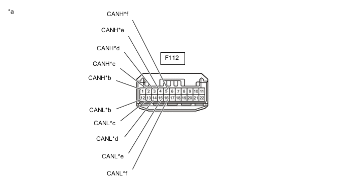
*a Front view of wire harness connector
(to No. 2 CAN Junction Connector)
*b to Clearance Warning ECU Assembly
(w/ TOYOTA Parking Assist-sensor System)
*c to Forward Recognition Camera
(w/ Toyota Safety Sense)
*d to Millimeter Wave Radar Sensor Assembly
(w/ Toyota Safety Sense)
*e to No. 11 CAN Junction Connector *f to Central Gateway ECU (Network Gateway ECU) -
Check the connection diagram of the components which are connected to the No. 2 CAN junction connector.
Terminal No. (Symbol) Wiring Color Connected to F112-1 (CANH) SB Clearance warning ECU assembly*1
(for Bus 1)
F112-12 (CANL) GR F112-2 (CANH) R Forward recognition camera*2
(for Bus 1)
F112-13 (CANL) GR F112-3 (CANH) G Millimeter wave radar sensor assembly*2
(for Bus 1)
F112-14 (CANL) GR F112-4 (CANH) B No. 11 CAN junction connector
(for Bus 1)
F112-15 (CANL) GR F112-5 (CANH) P Central gateway ECU (network gateway ECU)
(for Bus 1)
F112-16 (CANL) GR
-
*1: w/ TOYOTA Parking Assist-sensor System
-
*2: w/ Toyota Safety Sense
-
-
-
-
NO. 3 CAN JUNCTION CONNECTOR (w/ Stop and Start System)
-
Check the No. 3 CAN junction connector.
-
Connection diagram
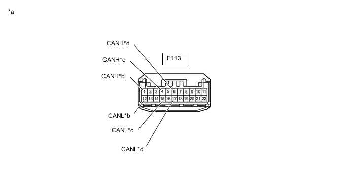
*a Front view of wire harness connector
(to No. 3 CAN Junction Connector)
*b to Central Gateway ECU (Network Gateway ECU) *c to ECM *d to Engine Stop and Start ECU -
Check the connection diagram of the components which are connected to the No. 3 CAN junction connector.
Terminal No. (Symbol) Wiring Color Connected to F113-1 (CANH) W Central gateway ECU (network gateway ECU)
(for Bus 2)
F113-12 (CANL) P F113-4 (CANH) GR ECM
(for Bus 2)
F113-15 (CANL) P F113-6 (CANH) R Engine stop and start ECU
(for Bus 2)
F113-17 (CANL) P
-
-
-
NO. 4 CAN JUNCTION CONNECTOR
-
Check the No. 4 CAN junction connector.
-
Connection diagram
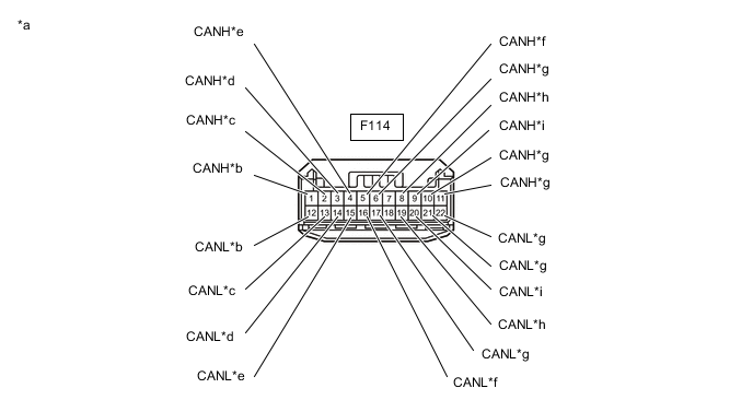
*a Front view of wire harness connector
(to No. 4 CAN Junction Connector)
*b to Combination Meter Assembly *c to Main Body ECU (Multiplex Network Body ECU) *d to Headlight ECU Sub-assembly LH
(for LED Headlight)
*e to Air Conditioning Amplifier Assembly *f to Certification ECU (Smart Key ECU Assembly)
(w/ Entry and Start System)
*g to Central Gateway ECU (Network Gateway ECU) *h to Telematics Transceiver
(w/ Manual (SOS) Switch)
*i to Radio and Display Receiver Assembly
(for Radio and Display Type)
- - -
Check the connection diagram of the components which are connected to the No. 4 CAN junction connector.
Terminal No. (Symbol) Wiring Color Connected to F114-1 (CANH) V Combination meter assembly
(for Bus 5)
F114-12 (CANL) SB F114-2 (CANH) G Main body ECU (multiplex network body ECU)
(for Bus 5)
F114-13 (CANL) SB F114-3 (CANH) L Headlight ECU sub-assembly LH*1
(for Bus 5)
F114-14 (CANL) SB F114-4 (CANH) P Air conditioning amplifier assembly
(for Bus 5)
F114-15 (CANL) SB F114-5 (CANH) R Certification ECU (smart key ECU assembly)*2
(for Bus 5)
F114-16 (CANL) SB F114-6 (CANH) B Central gateway ECU (network gateway ECU)
(for Bus 5)
F114-17 (CANL) SB F114-8 (CANH) GR Telematics transceiver*3
(for Bus 3)
F114-19 (CANL) LG F114-9 (CANH) B Radio and display receiver assembly*4
(for Bus 3)
F114-20 (CANL) LG F114-10 (CANH) G Central gateway ECU (network gateway ECU)
(for Bus 3)
F114-21 (CANL) LG F114-11 (CANH) V Central gateway ECU (network gateway ECU)
(for Bus 3)
F114-22 (CANL) LG
-
*1: for LED Headlight
-
*2: w/ Entry and Start System
-
*3: w/ Manual (SOS) Switch
-
*4: for Radio and Display Type
-
-
-
-
NO. 5 CAN JUNCTION CONNECTOR (for RHD)
-
Check the No. 5 CAN junction connector.
-
Connection diagram
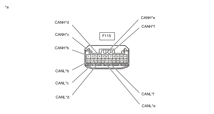
*a Front view of wire harness connector
(to No. 5 CAN Junction Connector)
*b to Airbag Sensor Assembly *c to Power Steering ECU Assembly *d to 4WD ECU Assembly
(for AWD)
*e to Steering Sensor *f to No. 7 CAN Junction Connector -
Check the connection diagram of the components which are connected to the No. 5 CAN junction connector.
Terminal No. (Symbol) Wiring Color Connected to F115-1 (CANH) B Airbag sensor assembly
(for Bus 4)
F115-12 (CANL) W F115-3 (CANH) P Power steering ECU assembly
(for Bus 4)
F115-14 (CANL) W F115-4 (CANH) L 4WD ECU assembly*1
(for Bus 4)
F115-15 (CANL) W F115-5 (CANH) BE Steering sensor
(for Bus 4)
F115-16 (CANL) W F115-6 (CANH) GR No. 7 CAN junction connector
(for Bus 4)
F115-17 (CANL) W
-
*1: for AWD
-
-
-
-
NO. 7 CAN JUNCTION CONNECTOR (for RHD)
-
Check the No. 7 CAN junction connector.
-
Connection diagram
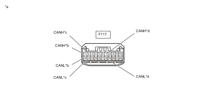
*a Front view of wire harness connector
(to No. 7 CAN Junction Connector)
*b to No. 5 CAN Junction Connector *c to Central Gateway ECU (Network Gateway ECU) *d to Brake Actuator Assembly -
Check the connection diagram of the components which are connected to the No. 7 CAN junction connector.
Terminal No. (Symbol) Wiring Color Connected to F117-1 (CANH) GR No. 5 CAN junction connector
(for Bus 4)
F117-12 (CANL) W F117-2 (CANH) B Central gateway ECU (network gateway ECU)
(for Bus 4)
F117-13 (CANL) W F117-7 (CANH) LG Brake actuator assembly
(for Bus 4)
F117-18 (CANL) W
-
-
-
NO. 9 CAN JUNCTION CONNECTOR (for LHD)
-
Check the No. 9 CAN junction connector.
-
Connection diagram
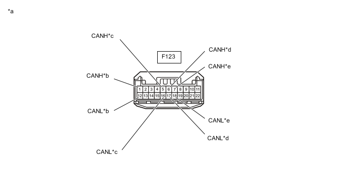
*a Front view of wire harness connector
(to No. 9 CAN Junction Connector)
*b to Airbag Sensor Assembly *c to Steering Sensor *d to Power Steering ECU Assembly *e to No. 10 CAN Junction Connector - - -
Check the connection diagram of the components which are connected to the No. 9 CAN junction connector.
Terminal No. (Symbol) Wiring Color Connected to F123-1 (CANH) B Airbag sensor assembly
(for Bus 4)
F123-12 (CANL) W F123-5 (CANH) BE Steering sensor
(for Bus 4)
F123-16 (CANL) W F123-6 (CANH) P Power steering ECU assembly
(for Bus 4)
F123-17 (CANL) W F123-7 (CANH) GR No. 10 CAN junction connector
(for Bus 4)
F123-18 (CANL) W
-
-
-
NO. 10 CAN JUNCTION CONNECTOR (for LHD)
-
Check the No. 10 CAN junction connector.
-
Connection diagram
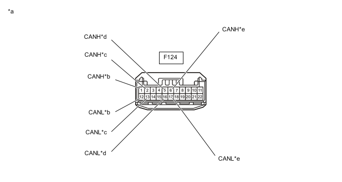
*a Front view of wire harness connector
(to No. 10 CAN Junction Connector)
*b to No. 9 CAN Junction Connector *c to Central Gateway ECU (Network Gateway ECU) *d to Brake Actuator Assembly *e to 4WD ECU Assembly
(for AWD)
- - -
Check the connection diagram of the components which are connected to the No. 10 CAN junction connector.
Terminal No. (Symbol) Wiring Color Connected to F124-1 (CANH) GR No. 9 CAN junction connector
(for Bus 4)
F124-12 (CANL) W F124-2 (CANH) B Central gateway ECU (network gateway ECU)
(for Bus 4)
F124-13 (CANL) W F124-5 (CANH) LG Brake actuator assembly
(for Bus 4)
F124-16 (CANL) W F124-6 (CANH) L 4WD ECU assembly*1
(for Bus 4)
F124-17 (CANL) W
-
*1: for AWD
-
-
-
-
NO. 11 CAN JUNCTION CONNECTOR (w/ Blind Spot Monitor System)
-
Check the No. 11 CAN junction connector.
-
Connection diagram
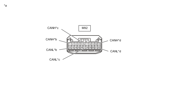
*a Front view of wire harness connector
(to No. 11 CAN Junction Connector)
*b to Central Gateway ECU (Network Gateway ECU) *c to Blind Spot Monitor Sensor LH *d to No. 2 CAN Junction Connector -
Check the connection diagram of the components which are connected to the No. 11 CAN junction connector.
Terminal No. (Symbol) Wiring Color Connected to M92-1 (CANH) R Central gateway ECU (network gateway ECU)
(for Bus 1)
M92-12 (CANL) GR M92-6 (CANH) G Blind spot monitor sensor LH
(for Bus 1)
M92-17 (CANL) GR M92-11 (CANH) B No. 2 CAN junction connector
(for Bus 1)
M92-22 (CANL) GR
-
-
-
DLC3
-
Disconnect the cable from the negative (-) battery terminal.
-
Measure the resistance according to the value(s) in the table below.
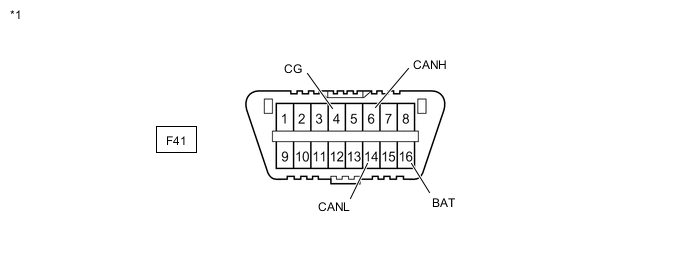
*1 DLC3 - -
-
-
CENTRAL GATEWAY ECU (NETWORK GATEWAY ECU)
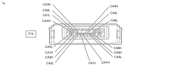
*a Component without harness connected
(Central Gateway ECU (Network Gateway ECU))
- -
-
Disconnect the cable from the negative (-) battery terminal.
-
Disconnect the F74 central gateway ECU (network gateway ECU) connector.
-
Measure the resistance according to the value(s) in the table below.
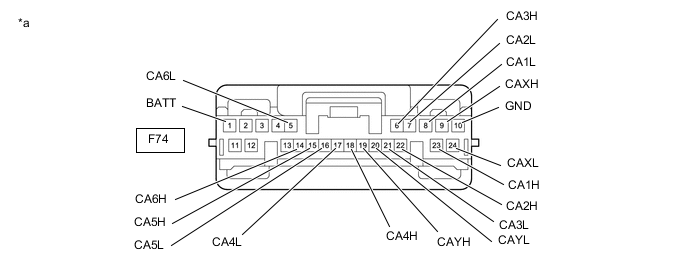
*a Front view of wire harness connector
(to Central Gateway ECU (Network Gateway ECU))
- -
-
-
STEERING SENSOR
-
Disconnect the cable from the negative (-) battery terminal.
-
Disconnect the F69 steering sensor connector.
-
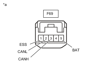
*a Front view of wire harness connector
(to Steering Sensor)
Measure the resistance according to the value(s) in the table below.
-
-
ECM (for 8NR-FTS)
Refer to Terminals of ECU.
-
Disconnect the cable from the negative (-) battery terminal.
-
Disconnect the A38 and C62 ECM connectors.
-
Measure the resistance according to the value(s) in the table below.
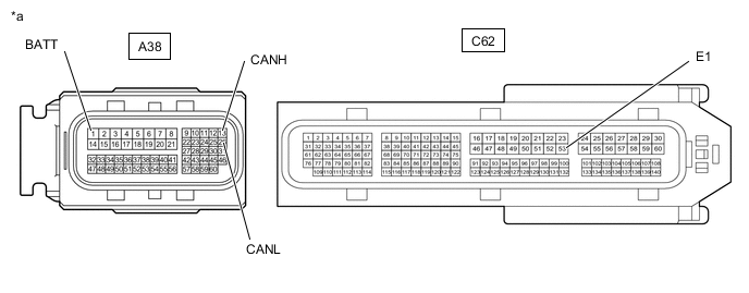
*a Front view of wire harness connector
(to ECM)
- -
-
-
ECM (for 3ZR-FAE)
Refer to Terminals of ECU.
-
Disconnect the cable from the negative (-) battery terminal.
-
Disconnect the A38 and C63 ECM connectors.
-
Measure the resistance according to the value(s) in the table below.
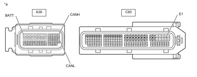
*a Front view of wire harness connector
(to ECM)
- -
-
-
COMBINATION METER ASSEMBLY
Refer to Terminals of ECU.
-
Disconnect the cable from the negative (-) battery terminal.
-
Disconnect the F4 combination meter assembly connector.
-
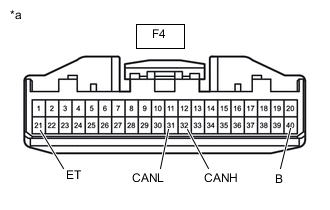
*a Front view of wire harness connector
(to Combination Meter Assembly)
Measure the resistance according to the value(s) in the table below.
-
-
BRAKE ACTUATOR ASSEMBLY
Refer to Terminals of ECU.
-
Disconnect the cable from the negative (-) battery terminal.
-
Disconnect the A42 brake actuator assembly connector.
-
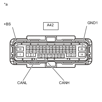
*a Front view of wire harness connector
(to Brake Actuator Assembly)
Measure the resistance according to the value(s) in the table below.
-
-
MAIN BODY ECU (MULTIPLEX NETWORK BODY ECU)
Refer to Terminals of ECU.
-
Disconnect the cable from the negative (-) battery terminal.
-
Disconnect the F15 main body ECU (multiplex network body ECU) connector.
-
Measure the resistance according to the value(s) in the table below.
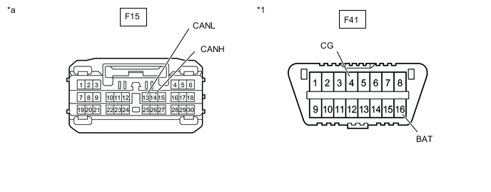
*1 DLC3 - - *a Front view of wire harness connector
(to Main Body ECU (Multiplex Network Body ECU))
- -
-
-
CERTIFICATION ECU (SMART KEY ECU ASSEMBLY) (w/ Entry and Start System)
Refer to Terminals of ECU.
-
Disconnect the cable from the negative (-) battery terminal.
-
Disconnect the F1 certification ECU (smart key ECU assembly) connector.
-
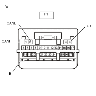
*a Front view of wire harness connector
(to Certification ECU (Smart Key ECU Assembly))
Measure the resistance according to the value(s) in the table below.
-
-
POWER STEERING ECU ASSEMBLY
Refer to Terminals of ECU.
-
Disconnect the cable from the negative (-) battery terminal.
-
Disconnect the F23 and F68 power steering ECU assembly connectors.
-
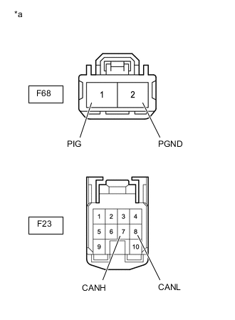
*a Front view of wire harness connector
(to Power Steering ECU Assembly)
Measure the resistance according to the value(s) in the table below.
-
-
CLEARANCE WARNING ECU ASSEMBLY (w/ TOYOTA Parking Assist-sensor System)
Refer to Terminals of ECU.
-
w/ Simple Intelligent Parking Assist System: Click here
-
w/o Simple Intelligent Parking Assist System: Click here
-
Disconnect the cable from the negative (-) battery terminal.
-
Disconnect the F38 clearance warning ECU assembly connector.
-
Measure the resistance according to the value(s) in the table below.
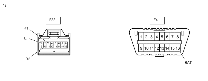
*1 DLC3 - - *a Front view of wire harness connector
(to Clearance Warning ECU Assembly)
- -
-
-
AIRBAG SENSOR ASSEMBLY
Refer to Terminals of ECU.
-
Disconnect the cable from the negative (-) battery terminal.
-
Disconnect the F70 airbag sensor assembly connector.
-
Measure the resistance according to the value(s) in the table below.
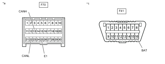
*1 DLC3 - - *a Front view of wire harness connector
(to Airbag Sensor Assembly)
- -
-
-
AIR CONDITIONING AMPLIFIER ASSEMBLY (w/ Top-mounted Air Conditioner Pressure Sensor)
Refer to Terminals of ECU.
-
for Automatic Air Conditioning System: Click here
-
for Manual Air Conditioning System: Click here
-
Disconnect the cable from the negative (-) battery terminal.
-
Disconnect the F72 air conditioning amplifier assembly connector.
-
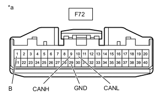
*a Front view of wire harness connector
(to Air Conditioning Amplifier Assembly)
Measure the resistance according to the value(s) in the table below.
-
-
AIR CONDITIONING AMPLIFIER ASSEMBLY (w/ Side-mounted Air Conditioner Pressure Sensor)
Refer to Terminals of ECU.
-
Disconnect the cable from the negative (-) battery terminal.
-
Disconnect the F73 air conditioning amplifier assembly connector.
-
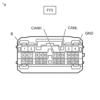
*a Front view of wire harness connector
(to Air Conditioning Amplifier Assembly)
Measure the resistance according to the value(s) in the table below.
-
-
RADIO AND DISPLAY RECEIVER ASSEMBLY (for Radio and Display Type)
Refer to Terminals of ECU.
-
Disconnect the cable from the negative (-) battery terminal.
-
Disconnect the F125 and F126 radio and display receiver assembly connectors.
-
Measure the resistance according to the value(s) in the table below.
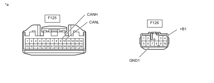
*a Front view of wire harness connector
(to Radio and Display Receiver Assembly)
- -
-
*1: w/ Top-mounted Air Conditioner Pressure Sensor without Stop and Start System
-
*2: w/ Side-mounted Air Conditioner Pressure Sensor
-
*3: w/ Stop and Start System
-
-
-
HEADLIGHT ECU SUB-ASSEMBLY LH (for LED Headlight)
Refer to Terminals of ECU.
-
Disconnect the cable from the negative (-) battery terminal.
-
Disconnect the A16 headlight ECU sub-assembly LH connector.
-
Measure the resistance according to the value(s) in the table below.
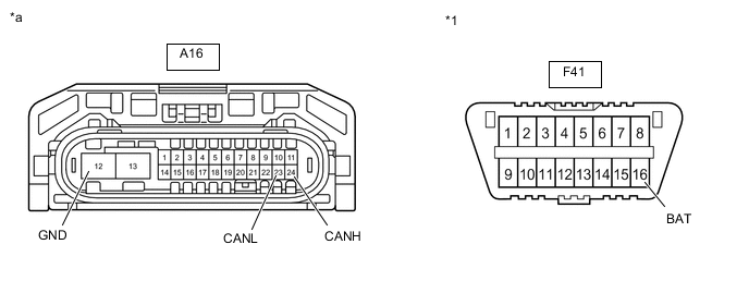
*1 DLC3 - - *a Front view of wire harness connector
(to Headlight ECU Sub-assembly LH)
- -
-
-
BLIND SPOT MONITOR SENSOR LH (w/ Blind Spot Monitor System)
Refer to Terminals of ECU.
-
Disconnect the cable from the negative (-) battery terminal.
-
Disconnect the M62 blind spot monitor sensor LH connector.
-
Measure the resistance according to the value(s) in the table below.
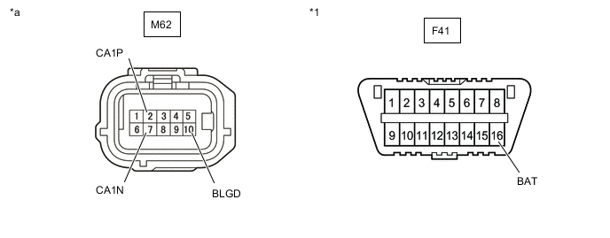
*1 DLC3 - - *a Front view of wire harness connector
(to Blind Spot Monitor Sensor LH)
- -
-
-
FORWARD RECOGNITION CAMERA (w/ Toyota Safety Sense)
Refer to Terminals of ECU.
-
Disconnect the cable from the negative (-) battery terminal.
-
Disconnect the R5 forward recognition camera connector.
-
Measure the resistance according to the value(s) in the table below.
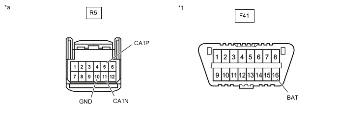
*1 DLC3 - - *a Front view of wire harness connector
(to Forward Recognition Camera)
- -
-
-
MILLIMETER WAVE RADAR SENSOR ASSEMBLY (w/ Toyota Safety Sense)
Refer to Terminals of ECU.
-
Disconnect the cable from the negative (-) battery terminal.
-
Disconnect the A2 millimeter wave radar sensor assembly connector.
-
Measure the resistance according to the value(s) in the table below.
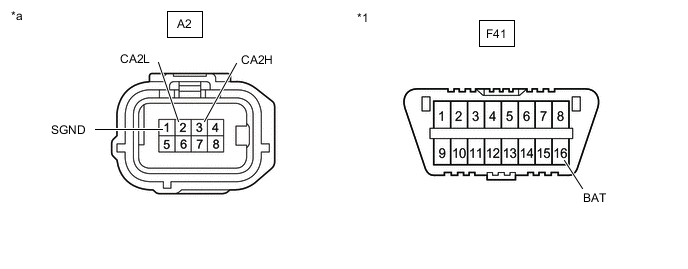
*1 DLC3 - - *a Front view of wire harness connector
(to Millimeter Wave Radar Sensor Assembly)
- -
-
-
ENGINE STOP AND START ECU (w/ Stop and Start System)
Refer to Terminals of ECU.
-
Disconnect the cable from the negative (-) battery terminal.
-
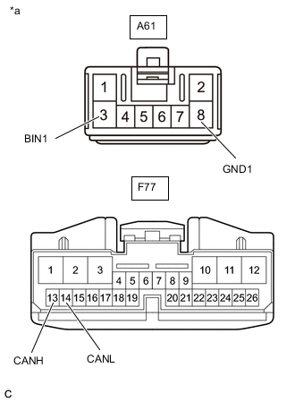
*a Front view of wire harness connector
(to Engine Stop and Start ECU)
Disconnect the A61 and F77 engine stop and start ECU connectors.
-
Measure the resistance according to the value(s) in the table below.
-
-
TELEMATICS TRANSCEIVER (w/ Manual (SOS) Switch)
Refer to Terminals of ECU.
-
Disconnect the cable from the negative (-) battery terminal.
-
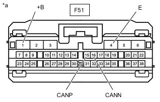
*a Front view of wire harness connector
(to Telematics Transceiver)
Disconnect the F51 telematics transceiver connector.
-
Measure the resistance according to the value(s) in the table below.
-
-
4WD ECU ASSEMBLY (for AWD)
Refer to Terminals of ECU.
-
Disconnect the cable from the negative (-) battery terminal.
-
Disconnect the M77 4WD ECU assembly connector.
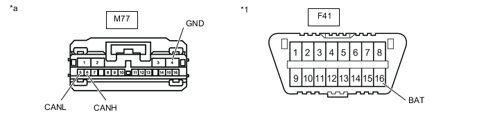
*1 DLC3 - - *a Front view of wire harness connector
(to 4WD ECU Assembly)
- - -
Measure the resistance according to the value(s) in the table below.
-