MAYDAY SWITCH INSPECTION
PROCEDURE
-
INSPECT MAYDAY SWITCH ASSEMBLY
-
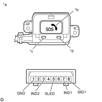
*a Component without harness connected
(Mayday Switch Assembly)
*b SOS Switch *c Green Indicator *d Red Indicator Check the resistance.
-
Measure the resistance according to the value(s) in the table below.
Standard Resistance Tester Connection Condition Specified Condition 8 (SIG1) - 1 (GND) Mayday switch is pushed 78 to 86 Ω 8 (SIG1) - 1 (GND) Mayday switch is not pushed 392 to 432 Ω If the resistance is not as specified, replace the mayday switch assembly.
-
-
Check the switch illumination.
-
Apply battery voltage to the mayday switch assembly and check that the illumination comes on.
OK Battery Connection Specified Condition Battery positive (+) → 5 (SLED)
Battery negative (-) → 1 (GND)
SOS switch comes on If the resistance is not as specified, replace the mayday switch assembly.
-
-
Check the indicator illumination.
-
Apply battery voltage to the mayday switch assembly and check that the illumination comes on.
OK Battery Connection Specified Condition Battery positive (+) → 7 (IND1)
Battery negative (-) → 1 (GND)
Red indicator comes on Battery positive (+) → 3 (IND2)
Battery negative (-) → 1 (GND)
Green indicator comes on If the resistance is not as specified, replace the mayday switch assembly.
-
-