TELEMATICS SYSTEM Emergency Call Switch Illumination Circuit
WIRING DIAGRAM
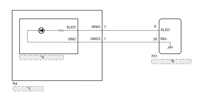
| *a | Mayday Switch Assembly (Manual (SOS) Switch) |
| *b | Telematics Transceiver |
| *c | Map Light Assembly |
CAUTION / NOTICE / HINT
Note
Depending on the parts that are replaced during vehicle inspection or maintenance, performing initialization, registration or calibration may be needed. Refer to Registration for Telematics System.
PROCEDURE
-
INSPECT MAP LIGHT ASSEMBLY
-
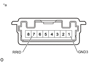
*a Component without harness connected
(Map Light Assembly)
Remove the map light assembly.
-
Connect 4 dry-cell batteries (1.5 V each) in series.
-
Connect a positive (+) from the batteries lead to terminal 7 (RRDI) and a negative (-) lead to terminal 1 (GND3) of the map light assembly (manual (SOS) switch) connector.
-
Check if the manual (SOS) switch illuminates.
OK Manual (SOS) switch illuminates. Result Proceed to OK NG
NG 
REPLACE MAP LIGHT ASSEMBLY Click here
OK 
-
-
INSPECT MAYDAY SWITCH ASSEMBLY (MANUAL (SOS) SWITCH)
-
Remove the mayday switch assembly (manual (SOS) switch).
-
Inspect the mayday switch assembly (manual (SOS) switch).
Result Proceed to OK NG
NG
REPLACE MAYDAY SWITCH ASSEMBLY Click here
OK
-
-
CHECK HARNESS AND CONNECTOR (TELEMATICS TRANSCEIVER - MAP LIGHT ASSEMBLY (MANUAL (SOS) SWITCH))
-
Disconnect the F51 telematics transceiver connector.
-
Disconnect the R4 map light assembly.
-
Measure the resistance according to the value(s) in the table below.
Standard Resistance Tester Connection Condition Specified Condition F51-9 (SLED) - R4-7 (RRID) Always Below 1 Ω F51-26 (SIG-) - R4-1 (GND3) Always Below 1 Ω F51-9 (SLED) or R4-7 (RRID) - Body ground Always 10 kΩ or higher F51-26 (SIG-) or R4-1 (GND3) - Body ground Always 10 kΩ or higher Result Proceed to OK NG
OK
REPLACE TELEMATICS TRANSCEIVER Click here
NG
REPAIR OR REPLACE HARNESS OR CONNECTOR
-