TOYOTA PARKING ASSIST-SENSOR SYSTEM(w/ Simple Intelligent Parking Assist System), Diagnostic DTC:C1625
| DTC Code | DTC Name |
|---|---|
| C1625 | Open or Short in Steering Angle Sensor +B |
DESCRIPTION
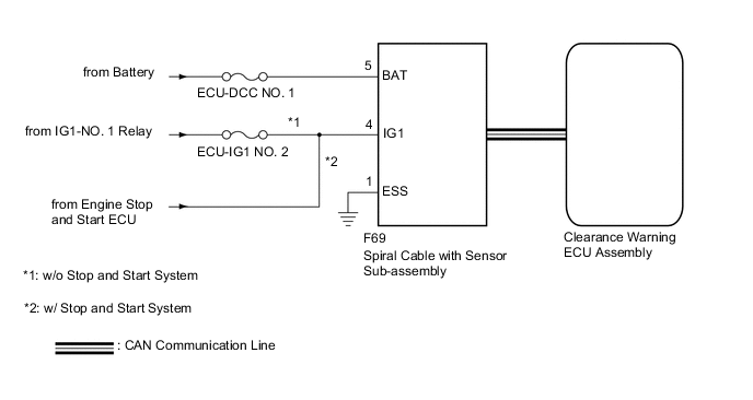
This DTC is stored when the clearance warning ECU assembly receives a steering angle sensor power supply malfunction signal via CAN communication from the spiral cable with sensor sub-assembly.
| DTC No. | Detection Item | DTC Detection Condition | Trouble Area |
|---|---|---|---|
| C1625 | Open or Short in Steering Angle Sensor +B | Either condition is met (1 trip detection logic*1):
|
|
-
*1: Only output while a malfunction is present.
-
*2: w/ Stop and Start System
| Vehicle Condition | |||
|---|---|---|---|
| Pattern 1 | Pattern 2 | ||
| Diagnosis Condition | Ignition switch ON | ○ | ○ |
| Malfunction Status | Open in steering angle sensor power source | ○ | - |
| Short in steering angle sensor power source | - | ○ | |
| Detection Time | - | - | |
| Number of Trips | 1 trip | 1 trip | |
Tech Tips
DTC will be output when conditions for either of the patterns in the table above are met.
WIRING DIAGRAM
CAUTION / NOTICE / HINT
Note
-
Inspect the fuses for circuits related to this system before performing the following procedure.
-
Depending on the parts that are replaced during vehicle inspection or maintenance, performing initialization may be needed. Refer to Calibration.
PROCEDURE
-
CHECK HARNESS AND CONNECTOR (SPIRAL CABLE WITH SENSOR SUB-ASSEMBLY - BODY GROUND)
-
Disconnect the spiral cable with sensor sub-assembly connector.
-
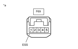
*a Front view of wire harness connector
(to Spiral Cable with Sensor Sub-assembly)
Measure the resistance according to the value(s) in the table below.
Standard Resistance Tester Connection Condition Specified Condition F69-1 (ESS) - Body ground Always Below 1 Ω Result Proceed to OK NG
NG 
REPAIR OR REPLACE HARNESS OR CONNECTOR
OK 
-
-
CHECK HARNESS AND CONNECTOR (SPIRAL CABLE WITH SENSOR SUB-ASSEMBLY BATTERY POWER SUPPLY)
-
Disconnect the spiral cable with sensor sub-assembly connector.
-
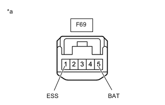
*a Front view of wire harness connector
(to Spiral Cable with Sensor Sub-assembly)
Measure the voltage according to the value(s) in the table below.
Standard Voltage Tester Connection Condition Specified Condition F69-5 (BAT) - F69-1 (ESS) Always 11 to 14 V Result Proceed to OK NG
NG
REPAIR OR REPLACE HARNESS OR CONNECTOR
OK
-
-
CHECK HARNESS AND CONNECTOR (SPIRAL CABLE WITH SENSOR SUB-ASSEMBLY IG POWER SUPPLY)
-
Disconnect the spiral cable with sensor sub-assembly connector.
-
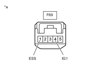
Measure the voltage according to the value(s) in the table below.
Standard Voltage Tester Connection Condition Specified Condition F69-4 (IG1) - F69-1 (ESS) Ignition switch ON 11 to 14 V*1
9.5 to 14 V*2
-
*1: w/o Stop and Start System
-
*2: w/ Stop and Start System
Result Result Proceed to OK A NG (w/o Stop and Start System) B NG (w/ Stop and Start System) C -
A
REPLACE SPIRAL CABLE WITH SENSOR SUB-ASSEMBLY Click here
B
REPAIR OR REPLACE HARNESS OR CONNECTOR
C
GO TO STOP AND START SYSTEM Click here
-