NAVIGATION SYSTEM, Diagnostic DTC:B15C0, B15C1
| DTC Code | DTC Name |
|---|---|
| B15C0 | GPS Antenna Disconnected (Short) |
| B15C1 | GPS Antenna Disconnected (Open) |
DESCRIPTION
These DTCs are stored when a malfunction occurs in the telephone antenna assembly.
| DTC No. | Detection Item | DTC Detection Condition | Trouble Area |
|---|---|---|---|
| B15C0 | GPS Antenna Disconnected (Short) | Navigation antenna error |
|
| B15C1 | GPS Antenna Disconnected (Open) | Error of the power source to the navigation antenna |
|
-
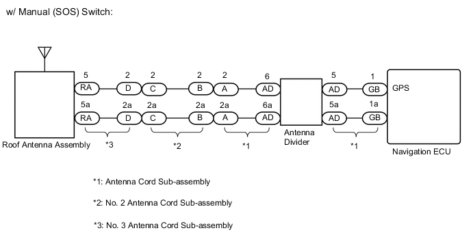
*1: w/ Manual (SOS) Switch
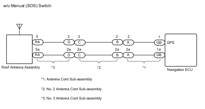
WIRING DIAGRAM
CAUTION / NOTICE / HINT
Note
Check that the wire harness is properly installed and does not have any sharp bends, pinching or loose connections.
PROCEDURE
-
CHECK DTC
-
Clear the DTCs.
Body Electrical > Navigation System > Clear DTCs -
Recheck for DTCs and check that no DTCs are output.
Body Electrical > Navigation System > Trouble CodesOK No DTCs are output. Result Proceed to OK NG
OK 
USE SIMULATION METHOD TO CHECK Click here
NG 
-
-
INSPECT NO. 3 ANTENNA CORD SUB-ASSEMBLY
-
Remove the No. 3 antenna cord sub-assembly.
-
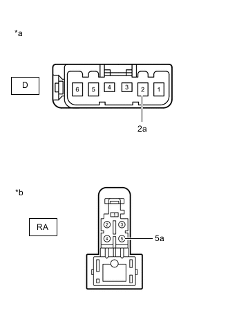
*a Front view of wire harness connector
(to No. 2 Antenna Cord Sub-assembly)
*b Front view of wire harness connector
(to Telephone Antenna Assembly)
Measure the resistance according to the value(s) in the table below.
Standard Resistance Tester Connection Condition Specified Condition D-2 - RA-5 Always Below 1 Ω D-2a - RA-5a Always Below 1 Ω D-2 or RA-5 - Body ground Always 10 kΩ or higher D-2a or RA-5a - Body ground Always 10 kΩ or higher Result Proceed to OK NG
NG
REPLACE NO. 3 ANTENNA CORD SUB-ASSEMBLY Click here
OK
-
-
INSPECT NO. 2 ANTENNA CORD SUB-ASSEMBLY
-
Remove the No. 2 antenna cord sub-assembly.
-
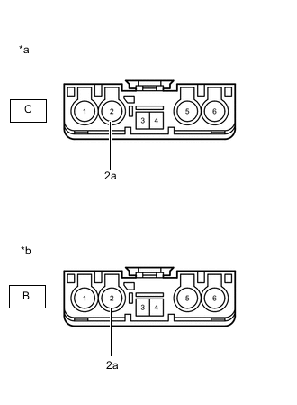
*a Front view of wire harness connector
(to No. 3 Antenna Cord Sub-assembly)
*b Front view of wire harness connector
(to Antenna Cord Sub-assembly)
Measure the resistance according to the value(s) in the table below.
Standard Resistance Tester Connection Condition Specified Condition C-2 - B-2 Always Below 1 Ω C-2a - B-2a Always Below 1 Ω C-2 or B-2 - Body ground Always 10 kΩ or higher C-2a or B-2a - Body ground Always 10 kΩ or higher Result Result Proceed to OK (w/ Manual (SOS) switch) A OK (w/o Manual (SOS) switch) B NG C
B 
INSPECT ANTENNA CORD SUB-ASSEMBLY Click here
C
REPLACE NO. 2 ANTENNA CORD SUB-ASSEMBLY Click here
A
-
-
INSPECT ANTENNA CORD SUB-ASSEMBLY (ANTENNA CORD SUB-ASSEMBLY - ANTENNA DIVIDER)
-
Remove the antenna cord sub-assembly.
-
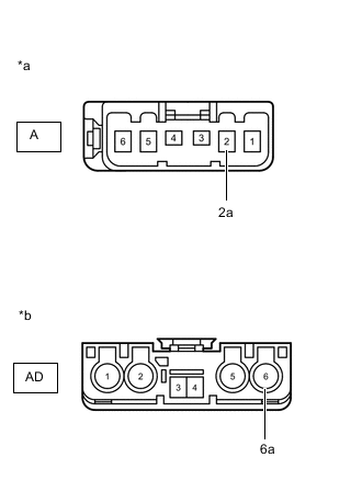
*a Front view of wire harness connector
(to No. 2 Antenna Cord Sub-assembly)
*b Front view of wire harness connector
(to Antenna Divider)
Measure the resistance according to the value(s) in the table below.
Standard Resistance Tester Connection Condition Specified Condition A-2 - AD-6 Always Below 1 Ω A-2a - AD-6a Always Below 1 Ω A-2 or AD-6 - Body ground Always 10 kΩ or higher A-2a or AD-6a - Body ground Always 10 kΩ or higher Result Proceed to OK NG
NG
REPLACE ANTENNA CORD SUB-ASSEMBLY Click here
OK
-
-
INSPECT ANTENNA DIVIDER
-
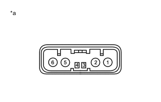
*a Component without harness connected
(Antenna Divider)
Remove the antenna divider.
-
Measure the resistance according to the value(s) in the table below.
Standard Resistance Tester Connection Condition Specified Condition 6 - 5 Always Below 1 Ω Result Proceed to OK NG
NG
REPLACE ANTENNA DIVIDER Click here
OK
-
-
INSPECT ANTENNA CORD SUB-ASSEMBLY (ANTENNA DIVIDER - NAVIGATION ECU)
-
Remove the antenna cord sub-assembly.
-
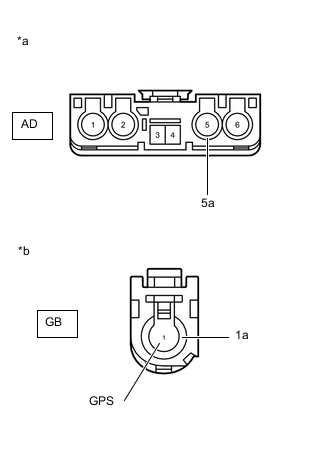
*a Front view of wire harness connector
(to Antenna Divider)
*b Front view of wire harness connector
(to Navigation ECU)
Measure the resistance according to the value(s) in the table below.
Standard Resistance Tester Connection Condition Specified Condition AD-5 - GB-1 (GPS) Always Below 1 Ω AD-5a - GB-1a Always Below 1 Ω AD-5 or GB-1 (GPS) - Body ground Always 10 kΩ or higher AD-5 or GB-1a - Body ground Always 10 kΩ or higher Result Proceed to OK NG
OK
GO TO STEP 8 Click here
NG
REPLACE ANTENNA CORD SUB-ASSEMBLY Click here
-
-
INSPECT ANTENNA CORD SUB-ASSEMBLY
-
Remove the antenna cord sub-assembly.
-
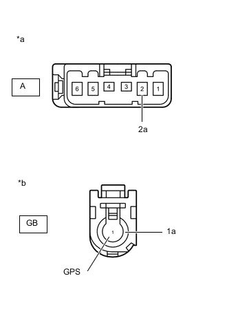
*a Front view of wire harness connector
(to No. 2 Antenna Cord Sub-assembly)
*b Front view of wire harness connector
(to Navigation ECU)
Measure the resistance according to the value(s) in the table below.
Standard Resistance Tester Connection Condition Specified Condition A-2 - GB-1 (GPS) Always Below 1 Ω A-2a - GB-1a Always Below 1 Ω A-2 or GB-1 (GPS) - Body ground Always 10 kΩ or higher A-2a or GB-1a - Body ground Always 10 kΩ or higher Result Proceed to OK NG
NG
REPLACE ANTENNA CORD SUB-ASSEMBLY Click here
OK
-
-
REPLACE ROOF ANTENNA ASSEMBLY
-
Replace the roof antenna assembly with a new or known good one.
-
Clear the DTCs.
Body Electrical > Navigation System > Trouble Codes -
Recheck for DTCs and check that no DTCs are output.
Body Electrical > Navigation System > Clear DTCsOK No DTCs are output. Result Proceed to OK NG
OK
END
NG
REPLACE NAVIGATION ECU Click here
-