NAVIGATION SYSTEM SYSTEM DESCRIPTION
-
NAVIGATION SYSTEM OUTLINE
-
Vehicle position tracking methods
It is essential that the navigation system correctly tracks the current vehicle position and displays it on the map. There are 2 methods to track the current vehicle position: autonomous (dead reckoning) and GPS* (satellite) navigation. Both navigation methods are used in conjunction with each other.*: GPS (Global Positioning System)
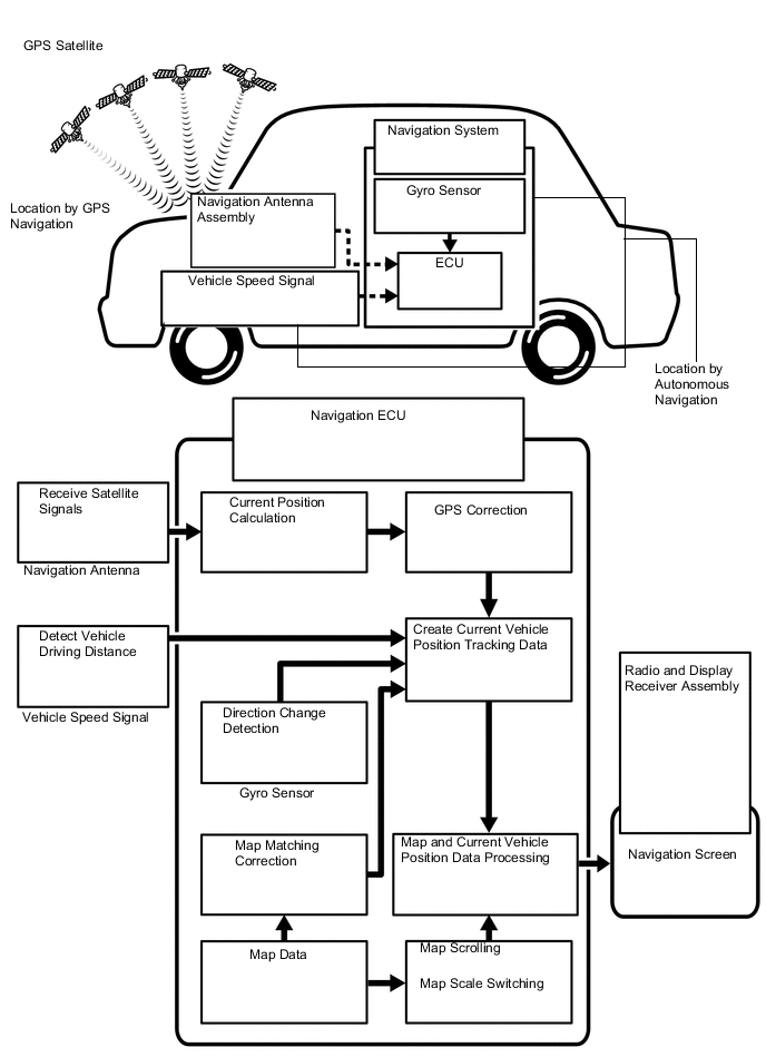
Operation Description Vehicle Position Calculation The navigation ECU calculates the current vehicle position (direction and current position) using the direction deviation signal from the gyro sensor and driving distance signal calculated from the vehicle speed signal and creates the driving route. Map Display Processing The navigation ECU processes the vehicle position data, vehicle driving track and map data from the internal memory. Map Matching The map data from the internal memory is compared to the vehicle position and driving track data. Then, the vehicle position is matched with the neare stroad. GPS Correction The vehicle position is matched to the position measured by the GPS. Then, the GPS measurement position data is compared with the vehicle position and driving track data. If the position is very different, the GPS measurement position is used. Distance Correction The vehicle speed signal includes errors caused by tire wear and slippage between the tires and road surface. Distance correction is performed to account for this. The navigation ECU automatically offsets the signal to make up for the difference between it and the distance data of the map. The offset is automatically updated. 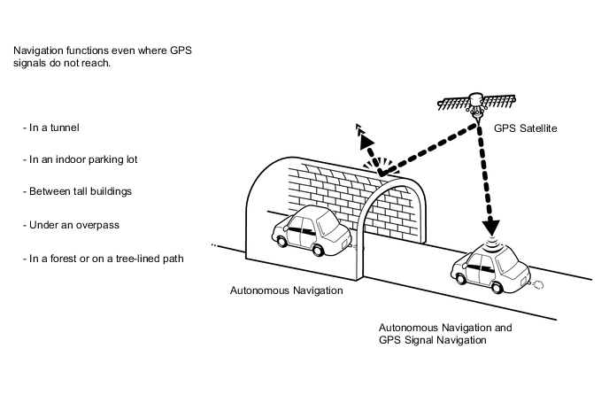
Tech Tips
The combination of autonomous and GPS navigation makes it possible to display the vehicle position even when the vehicle is in places where GPS signals cannot be received. When only autonomous navigation is used, however, the mapping accuracy may slightly decrease.
-
Autonomous navigation
This method determines the relative vehicle position based on the driving track determined by the gyro sensor located in the navigation ECU and the vehicle speed signal.
-
Gyro sensor
Used to calculate the direction by detecting angular velocity. It is located in the navigation ECU.
-
Vehicle speed signal
Used to calculate the vehicle driving distance.
-
-
GPS* navigation (Satellite navigation)
This method detects the absolute vehicle position using radio waves from GPS satellites.
*: GPS satellites were launched by the U.S. Department of Defense for military purposes.
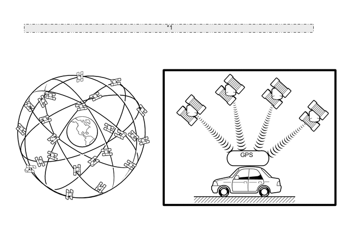
*1 Current longitude/latitude/altitude is determined using the signal arrival time from four satellites. Number of Satellites Measurement Description 2 or less Measurement is impossible Vehicle position cannot be obtained because the number of satellites is not enough. 3 2-dimensional measurement is possible Vehicle position is obtained based on the current longitude and latitude. (This is less precise than 3-dimensional measurement.) 4 3-dimensional measurement is possible Vehicle position is obtained based on the current longitude, latitude and altitude. -
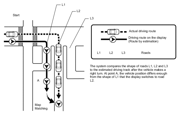
Map matching
The current driving route is calculated by autonomous navigation (according to the gyro sensor and vehicle speed signal) and GPS navigation. This information is then compared with possible roadshapes from the map data in the internal memory and the vehicle position is set onto the mostappropriate road.
-
-
TOUCH SWITCH OUTLINE
-
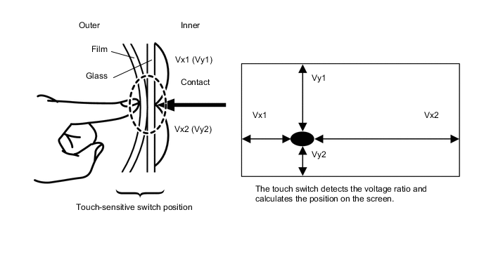
Touch switches are touch-sensitive (interactive) switches operated by touching the screen. When a switch is pressed, the outer film bends in to contact the inner glass at the pressed position. By doing this, the voltage ratio is measured and the pressed position is detected.
-
-
USB AUDIO SYSTEM FUNCTION OUTLINE
-
The No. 1 stereo jack adapter assembly is equipped with a USB connector. Connecting a USB device or "iPod" to the No. 1 stereo jack adapter assembly allows music files to be played. Not only is it possible to play music from a USB device with audio functions, it is also possible to play MP3, WMA or AAC music files that are stored on a USB device. In addition, "iPod" control software is installed, allowing file selection from playlists and operation using shuffle mode.
Tech Tips
Operation through the controls of a USB device or "iPod" cannot be performed while it is connected.
-
USB audio system compatible devices
-
USB device
The following device formats can be used:
Compatible USB device formats
-
USB communication format: USB 2.0 HS (480 Mbps) and FS (12 Mbps)
-
File format: FAT16/32 (Windows)
-
Class: Mass storage class
MP3, WMA and AAC files written to a USB device with any format other than those listed above may not be played correctly and their names and folder names may not be displayed correctly.
Items related to standards and limitations are as follows:
-
Maximum directory hierarchy: 8 levels
-
Maximum number of folders in device: 3000 (including the root folder)
-
Maximum number of files in device: 9999
-
Maximum number of files per folder: 255
-
-
"iPod"
"iPhone", "iPod", "iPod classic", "iPod nano" and "iPod touch" are trademarks of Apple Inc., registered in the U.S. and other countries.
The following "iPod", "iPod nano", "iPod classic", "iPod touch" and "iPhone" devices can be used with this system.
Made for:
-
"iPod touch" (5th generation)
-
"iPod touch" (4th generation)
-
"iPod touch" (3rd generation)
-
"iPod touch" (2nd generation)
-
"iPod touch" (1st generation)
-
"iPod classic" (except 5th generation)
-
"iPod nano" (7th generation)
-
"iPod nano" (6th generation)
-
"iPod nano" (5th generation)
-
"iPod nano" (4th generation)
-
"iPod nano" (3rd generation)
-
"iPod nano" (1st generation)
-
"iPhone 5"
-
"iPhone 4S"
-
"iPhone 4"
-
"iPhone 3GS"
-
"iPhone 3G"
-
"iPhone"
Tech Tips
Depending on differences between models or software versions etc., some models might be incompatible with this system.
-
-
-
-
MP3/WMA/AAC OUTLINE
-
Playable MP3 file standards
Compatible standard MPEG1 LAYER3, MPEG2 LSF LAYER3 Compatible sampling frequency
-
MPEG1 LAYER3: 32, 44.1, 48 (kHz)
-
MPEG2 LSF LAYER3: 16, 22.05, 24 (kHz)
Compatible bit rate
-
MPEG1 LAYER3: 32 to 320 (kbps)
-
MPEG2 LSF LAYER3: 8 to 160 (kbps)
-
Compatible with VBR
Compatible channel mode Stereo, joint stereo, dual channel, monaural -
-
Playable WMA file standards
Compatible standard WMA Ver. 7, 8, and 9 Compatible sampling frequency 32, 44.1, 48 (kHz) Compatible bit rate (Only compatible with 2-channel playback)
-
Ver. 7, 8: CBR48 to 192 (kbps)
-
Ver. 9: CBR48 to 320 (kbps)
-
Compatible with VBR
-
-
Playable AAC file standards
Compatible standard MPEG4/AAC-LC Compatible sampling frequency 11.025, 12, 16, 22.05, 24, 32, 44.1, 48 (kHz) Compatible bit rate
-
16 to 320 (kbps)
-
Compatible with VBR
-
-
ID3 tag, WMA tag and AAC tag
-
Additional text information called an ID3 tag can be input to MP3 files. Information such as song titles and artist names can be stored.
Tech Tips
This player is compatible with ID3 tags of ID3 Ver. 1.0 and 1.1, and ID3 Ver. 2.2 and 2.3. (Number of characters complies with ID3 Ver. 1.0 and 1.1.)
-
Additional text information called a WMA tag can be input to WMA files. Information such as song titles and artist names can be stored.
-
Additional text information called an AAC tag can be input to AAC files. Information such as song titles and artist names can be stored.
-
-
Usable media format
-
Standards and restrictions
Maximum directory levels 8 levels Maximum number of characters for a folder name/file name 32 characters Maximum number of folders 192 (Including empty folders, root folders, and folders that do not contain MP3/WMA/AAC files) Maximum number of files in a disc 255 (Including non-MP3/WMA/AAC files)
-
-
File names
-
Only files with an extension of ".mp3", ".wma" and ".m4a" can be recognized and played as MP3, WMA or AAC files.
-
Save MP3, WMA or AAC files with an extension of ".mp3", ".wma" or ".m4a".
Note
If non-MP3, non-WMA or non-AAC files are saved with an extension of ".mp3", ".wma" or ".m4a", those files may be wrongly recognized as MP3, WMA or AAC files and played. A loud noise may occur and damage to the speakers may result.
-
-
-
"Bluetooth" OUTLINE
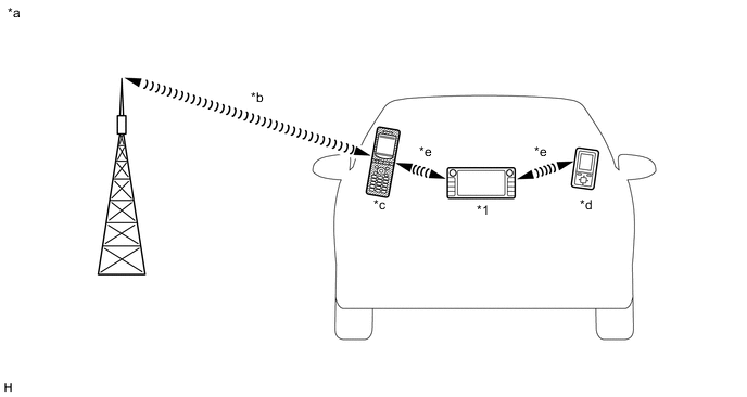
*1 Radio and Display Receiver Assembly
(Built-in "Bluetooth" Antenna)
- - *a Example *b Cellular Network *c Cellular Phone
("Bluetooth" Compatible Type)
*d Portable Audio Player
("Bluetooth" Compatible Type)
*e "Bluetooth" Wireless Connection - -
-
"Bluetooth" is a trademark owned by Bluetooth SIG, Inc.
-
"Bluetooth" is a wireless connection technology that uses the 2.4 GHz frequency band.
Tech Tips
The communication performance of "Bluetooth" may vary depending on obstructions or radio wave conditions between communication devices, electromagnetic radiation, communication device sensitivity or antenna capacity.
-
Hands-free function
-
The "Bluetooth" built-in radio and display receiver assembly and a "Bluetooth" compatible cellular phone* can be connected using a "Bluetooth" wireless connection. This enables the use of the hands-free function on the cellular phone even if the phone is in a pocket or bag. For this reason, it is not necessary to use a connector or cable to connect the cellular phone.
-
*: Some versions of "Bluetooth" compatible cellular phones may not function properly.
-
-
The hands-free function uses a "Bluetooth" wireless connection. A "Bluetooth" wireless connection can be affected by uncertain elements, such as vehicle location, time of day, etc. Therefore, problems related to establishing connection may be caused temporarily by "Bluetooth" connection conditions. It is necessary to check the frequency of occurrence, connection conditions using another cellular phone, etc. when performing diagnosis.
-
Compatible hands-free devices
Required "Bluetooth" specifications Ver. 1.1 or higher (Ver. 3.0+EDR recommended) Compatible profiles
-
HFP (Hands-Free Profile) Ver. 1.0 or higher (Ver. 1.6 or higher recommended)*1
-
PBAP (Phone Book Access Profile) Ver. 1.0 or higher (Ver. 1.1 or higher recommended)*1
-
MAP (Message Access Profile) Ver. 1.0 or higher*2
-
PAN (Personal Area Networking) Ver. 1.0 or higher*3
-
DUN (Dial-Up Networking Profile) Ver. 1.1 or higher*3
Maximum number of hands-free devices that can be registered (including audio devices) 4
-
*1: This profile is necessary when using the hands-free function.
*2: This profile is necessary when using the message function (w/ SMS/MMS/e-mail Function).
*3: This profile is necessary when using the connected services function (w/ Connected Services).
Tech Tips
The amount of remaining battery charge displayed on the radio and display receiver assembly may be different from that of the "Bluetooth" device.
-
-
-
"Bluetooth" audio function
-
The "Bluetooth" built-in radio and display receiver assembly and a "Bluetooth" compatible portable audio player* can be connected using a "Bluetooth" wireless connection. This enables files stored in the portable audio player to be heard from the vehicle speakers. In addition, operations such as play/stop can be performed directly from the radio and display receiver assembly.
-
*: Some versions of "Bluetooth" compatible audio players may not be able to be connected via the "Bluetooth" function, or music may play, but functions available using the radio and display receiver assembly may be limited.
-
-
Compatible "Bluetooth" audio devices
Required "Bluetooth" specifications Ver. 1.1 or higher (Ver. 3.0+EDR recommended) Compatible profiles
-
A2DP (Advanced Audio Distribution Profile) Ver. 1.0 or higher (Ver. 1.2 or higher recommended)
-
AVRCP (Audio/Video Remote Control Profile) Ver. 1.0 or higher (Ver. 1.4 or higher recommended)
Maximum number of audio devices that can be registered (including hands-free devices) 4 Tech Tips
The amount of remaining battery charge displayed on the radio and display receiver assembly may be different from that of the "Bluetooth" device.
-
-
-
-
NAVIGATION ECU OUTLINE
The navigation ECU resides in the vehicle. Inputs to the system are sent from the radio and display receiver assembly using LVDS communication, the GPS receiver through which the vehicle location isobtained, and connectivity via a "Bluetooth" enabled phone. The navigation ECU enables the use of exclusive applications.
-
"MirrorLink" FUNCTION OUTLINE (w/ "MirrorLink" Function)
-
"MirrorLink" is a function that enables the radio and display receiver assembly to operate applications on a smartphone which meets Car Connectivity Consortium standards by connecting the smartphone to the radio and display receiver assembly with a USB cable.
-
"MirrorLink" compatible smartphone manufacturers and applications are listed below.
MirrorLink Version Manufacturer Device Application Ver.1.0 Nokia 701, N8 or N9 Car Mode Samsung Galaxy S3 DriveLink Ver.1.1 or later For details, refer to http://carconnectivity.org/ and http://www.mirrorlink.com/ Tech Tips
-
Some applications require payment.
-
The names of applications are subject to change.
-
Some applications have a display restriction in consideration of safe driving.
-
-
-
CONNECTED SERVICES OUTLINE (w/ Connected Services)
-
The following services are available by connecting the navigation system to Toyota's portal site via the internet using a cellular phone.
-
Online search: New establishments, such as restaurants, bars, etc., that are not registered in the navigation system can be set as a destination.
-
Importing memory points: Establishments that were searched for using a personal computer can be set as a destination and can be registered as memory points.
Tech Tips
-
For known compatible phones, refer to www.my.toyota.eu.
-
It is necessary to agree to the terms of service for the search engine on www.my.toyota.eu. Failure to do so may cause problems such as not being able to select the search engine or the screen not transferring to the next screen when "Online search" is selected.
-
Connected services are available only on a navigation ECU that has had its identification code registered when the account was created.
-
Search results may not be displayed if the target establishment is not in the data supplied by the provider or in the map data of the navigation system.
-
As the information for a destination set using the connected services is supplied by the provider, the navigation system may guide to a location that deviates from the actual destination.
-
-
-
TRAFFIC AND PARKING INFORMATION FUNCTION OUTLINE (w/ Connected Services)
-
Traffic information, traffic prediction information and parking lot information can be viewed.
There are 2 methods to receive the above information.
Priority Method Information 1st Internet by using a cellular phone
-
TPEG-TEC (Traffic Event Compact)
-
TPEG-TFP (Traffic Flow Prediction)
2nd FM RDS-TMC (Radio Data System-Traffic Message Channel) Tech Tips
-
When RDS-TMC information and TPEG information can be received, TPEG information will be given priority.
-
When the source for traffic information is switched between RDS-TMC information and TPEG information, traffic information displayed on the map may change.
-
When the vehicle enters an area where TPEG information can be received, TPEG information can be received only after the vehicle has been driven for 1 km (0.6 miles) or more in the coverage area.
-
Traffic information is displayed only on a map with a scale of 13 km (8 miles) or less.
-
Detoured route search activates only when traffic information within 200 km (124 miles) exists.
-
If there is traffic information only for traffic congestion, the route may not be changed depending on the distance of the congestion.
-
If there is no available avoidance route, the route may not be changed.
-
Depending on provided data, the "From" and "To" information of the traffic event information may not be displayed.
-
Provided data may differ from the actual conditions.
-
-
-
RADIO DESCRIPTION
-
Radio frequency band
-
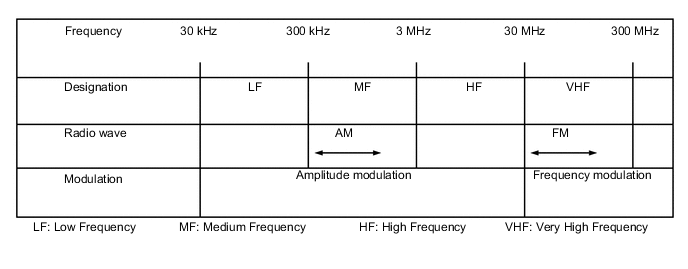
Radio broadcasts use the radio frequency bands shown in the table below.
-
-
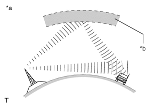
Service area
-
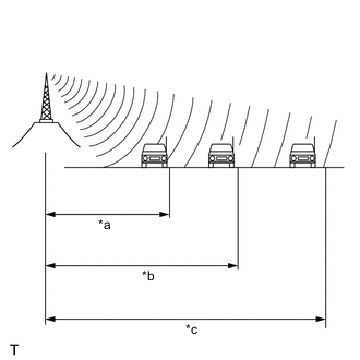
*a FM (Stereo) *b FM (Monaural) *c AM The service areas of AM and FM broadcasts are vastly different. Sometimes an AM broadcast can be received very clearly but an FM stereo broadcast cannot. FM stereo has the smallest service area, and is prone to pick up static and other types of interference such as noise.
-
-
Radio reception problems
Tech Tips
In addition to static, other problems such as "phasing", "multipath" and "fade out" exist. These problems are not caused by electrical noise, but by the radio signal propagation method itself.
-
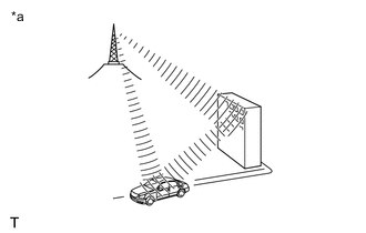
*a Phasing *b Ionosphere Phasing
AM broadcasts are susceptible to electrical interference and another kind of interference called phasing. Occurring only at night, phasing is the interference created when a vehicle receives 2 radio wave signals from the same transmitter. One signal is reflected off the ionosphere and the other signal is received directly from the transmitter.
-
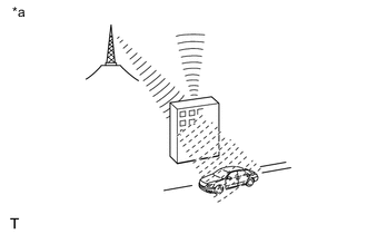
*a Multipath Multipath
Multipath is a type of interference created when a vehicle receives 2 radio wave signals from the same transmitter. One signal is reflected off buildings or mountains and the other signal is received directly from the transmitter.
-
*a Fade Out Fade out
Fade out is caused by objects (buildings, mountains and other large obstructions) that deflect part of a signal, resulting in a weaker signal when the object is between the transmitter and vehicle. High frequency radio waves, such as FM broadcasts, are easily deflected by obstructions. Low frequency radio waves, such as AM broadcasts, are less likely to be deflected.
-
-
Noise problem
Technicians must have a clear understanding about each customer's noise complaint. Use the following table to diagnose noise problems.
Radio Frequency Noise Occurrence Condition Presumable Cause AM Noise occurs in a specific area Foreign noise Noise occurs when listening to an intermittent broadcast An identical program transmitted from multiple towers can cause noise where the signals overlap Noise occurs only at night Signal phasing FM Noise occurs while driving in a specific area Multipath resulting from a change in FM frequency
-
-
VEHICLE CUSTOMIZATION OUTLINE
-
Customization of functions can also be customized on the multi-display screen. Refer to Owner's Manual for further information on customizable items for the audio and visual system.
Tech Tips
-
Items available for customization via the audio and visual system can also be customized by using the GTS.
-
Some customize parameters displayed on the GTS will be displayed on the vehicle customization screen for the audio and visual system. Users can customize these items.
-
-
-
DAB (DIGITAL AUDIO BROADCAST) FUNCTION OUTLINE (w/ DAB Function)
-
DAB (Digital Audio Broadcast) is the standard for digital radio. Compared to conventional FM/AM broadcasting, DAB enables higher sound quality radio broadcasting with lower noise when reception conditions change. DAB has an FM-Link function that automatically and temporarily changes the radio to the simultaneously broadcasted FM station if the DAB broadcasting reception level falls.
-
-
AUTOMATIC SOUND LEVELIZER (ASL) FUNCTION OUTLINE
-
The Automatic Sound Levelizer (ASL) function automatically adjusts the audio system volume level in order to compensate for increased vehicle noise (vehicle noise tends to increase as vehicle speed increases). The ASL adjusts the volume level based upon vehicle speed signals sent from the combination meter assembly.
-
-
COMMUNICATION SYSTEM
-
CAN Communication Outline
-
The audio and visual system uses CAN communication between the radio and display receiver assembly and ECUs.
-
-
AVC-LAN Outline (for 9 Speakers)
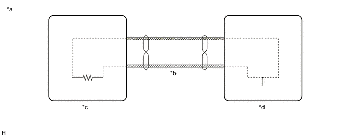
*a Example *b AVC-LAN Communication Line *c Master Unit *d Slave Unit
-
Components of the audio and visual system communicate with each other via AVC-LAN communication.
-
The AVC-LAN uses a twisted pair of wires for its communication lines.
-
The master unit of the AVC-LAN is the radio and display receiver assembly.
Tech Tips
-
The radio and display receiver assembly has the resistance (60 to 80 Ω) necessary for communication.
-
If a short or open occurs in the AVC-LAN circuit, communication is interrupted and the system will not operate normally.
-
-
-
Local Bus Communication Outline
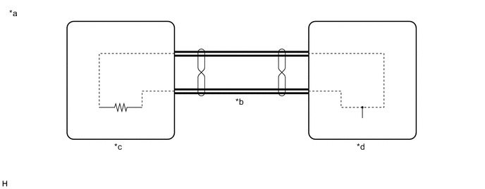
*a Example *b Local Bus Communication Line *c Master Unit *d Slave Unit
-
Components of the audio and visual system communicate with each other via the local bus.
-
The local bus uses a twisted pair of wires for its communication lines.
-
The master unit of the local bus is the radio and display receiver assembly.
Tech Tips
-
The radio and display receiver assembly has the resistance (108 to 132 Ω) necessary for communication.
-
If a short or open occurs in the local bus circuit, communication is interrupted and the system will not operate normally.
-
-
-
CAN Communication Outline
-
The navigation system uses CAN communication between the radio and display receiver assembly and ECUs.
-
-
LVDS Communication Outline
-
The navigation system uses LVDS communication between the radio and display receiver assembly and navigation ECU.
-
If a short or open occurs in the LVDS communication line, communication is interrupted and the system will not operate normally.
-
-
-
DIAGNOSTIC FUNCTION OUTLINE
-
The audio and visual system has a diagnostic function (the result is indicated on the master unit).
-
-
MOBILE ASSISTANT FUNCTION OUTLINE (w/ Mobile Assistant Function)
-
This function can be used when a compatible smartphone with an appropriate speech recognition application is connected to the radio and display receiver assembly via "Bluetooth".
-
-
"Wi-Fi" OUTLINE (w/ "Wi-Fi" Function)
-
"Wi-Fi" is a worldwide wireless communication standard widely used as a short range communication tool.
-
"Wi-Fi" is a trademark owned by Wi-Fi Alliance, a non-profit industry association.
-
The Radio and Display Receiver Assembly uses the 2.4 GHz frequency band for "Wi-Fi" communication.
Tech Tips
The communication performance of "Wi-Fi" may vary depending on obstructions or radio wave conditions between communication devices, electromagnetic radiation, communication device sensitivity or antenna capacity.
-