INSTRUMENT PANEL SPEAKER INSPECTION
PROCEDURE
-
INSPECT FRONT NO. 2 SPEAKER ASSEMBLY (w/ Woofer)
-
Check the resistance.
-
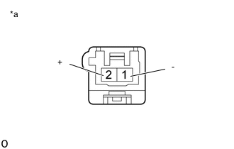
*a Component without harness connected
(Front No. 2 Speaker Assembly)
Measure the resistance according to the value(s) in the table below.
Standard Resistance Tester Connection Condition Specified Condition 2 (+) - 1 (-) Always 6.8 to 10.2 Ω If the result is not as specified, replace the front No. 2 speaker assembly.
-
-
-
INSPECT FRONT NO. 2 SPEAKER ASSEMBLY (w/o Woofer)
-
Check the resistance.
-
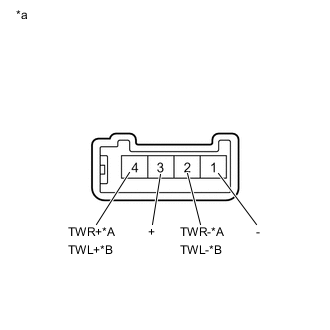
*A for RH *B for LH *a Component without harness connected
(Front No. 2 Speaker Assembly)
Measure the resistance according to the value(s) in the table below.
Standard Resistance for RH Tester Connection Condition Specified Condition 4 (TWR+) - 2 (TWR-) Always 10 kΩ or higher 1 (-) - 2 (TWR-) Always Below 1 Ω 3 (+) - 4 (TWR+) Always Below 1 Ω for LH Tester Connection Condition Specified Condition 4 (TWL+) - 2 (TWL-) Always 10 kΩ or higher 1 (-) - 2 (TWL-) Always Below 1 Ω 3 (+) - 4 (TWL+) Always Below 1 Ω If the result is not as specified, replace the front No. 2 speaker assembly.
-
-